


3 INSTALLATION AND CONNECTIONS
10 English
INTRODUCTION
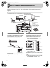
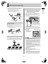
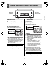
z Connect the cable of the wired remote control (VA-
RMN01) (sold separately) to the remote control input
terminals (among the control terminals).
Cut the plug off the cord, and connect the red wire to
“REMOTE” and the bare wire to “C”.
(1) Push in the lock pin with a flat-blade screwdriver.
(2) Insert the cable.
(3) Pull out the lock pin with a flat-blade screwdriver. The
cable is now fixed in place.
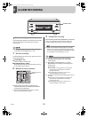
The VA-SW81LITE/VA-SW814 application software lets
you control the digital video recorder, and monitor live
images, recorded images and audio through a network.
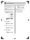
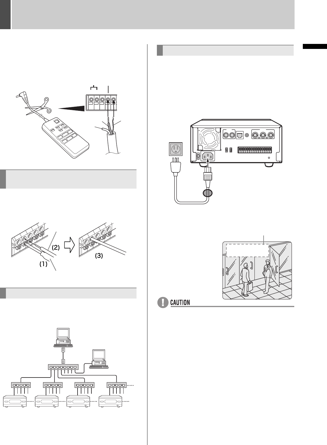
1 When you have finished making all the
other connections, insert the power
plug into the wall outlet.
There is no power switch. The POWER indicator lights,
then all the indicators on the front panel flash for
approximately 30 seconds. The monitor screen displays
the camera image.
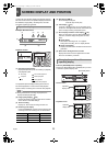
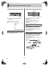
z When turning the power ON for the first time
“PLEASE SET THE CLOCK” is displayed on the monitor
screen. Follow the steps on P.12 to set the clock.
z If the clock is
already set
The operation display
area is displayed.
z If the POWER indicator flashes
The digital video recorder has a self-check function that
detects problems. If there is a problem at power ON or
during operation, the type of problem is indicated by how
rapidly the POWER indicator flashes. Contact a Sanyo
Authorized Service Center if the POWER indicator flashes.
4 flashes per second:
The hard disk is checked automatically at power ON. If
a hard disk problem is found, the POWER indicator
flashes, and the hard disk must be replaced or initialized.
If you need to save images stored on the disk, contact a
Sanyo Authorized Service Center.
1 flash per second:
Fan problem
z If you disconnect the power cable
Don’t move the digital video recorder for 30 seconds
after power OFF.
The disk in the hard disk drive briefly keeps spinning
after power OFF due to inertia, during which time the
head is unstable. At this time, the disk is sensitive to
shocks or vibrations, so avoid even light shocks.
Connecting cables to the control and
alarm terminals
Connecting to a network
RS485
REMOTE
ABC C
Bare wire
Red wire
White
wire
VA-RMN01
Cable
Flat-blade screwdriver
SWITCH
SWITCH SWITCH SWITCH SWITCH
PC
DVR DVR DVR DVR
PC
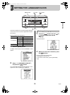
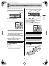
Connecting the power cord
ALL
RESET
LAN
MIC IN
OUT
IN
OUT
TV SYSTEM
NTSC
PAL
*
*
Attach the supplied ferrite
core to the base of the power
cable (coiling not necessary).
Operation display area
HI A
20-05-04 AL 00015
08:30:45 ----------
e00_l8hae_xe_7.book Page 10 Monday, July 5, 2004 10:02 AM