104 Fibre Channel Interface Manual, Rev. D
10.3 8067 mode
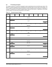
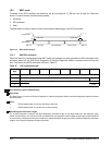
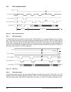
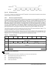
Transfers on an 8067 interface are started by the drive pulling the –P_ESI pin low to enter the Discovery
phase. For each transfer, there are three phases:
1. Discovery
2. ESI command
3. Data
The data phase is either a read or write to the enclosure depending on the SCSI command.
Figure 14. ESI transfer phases
10.3.1 8067 ESI command
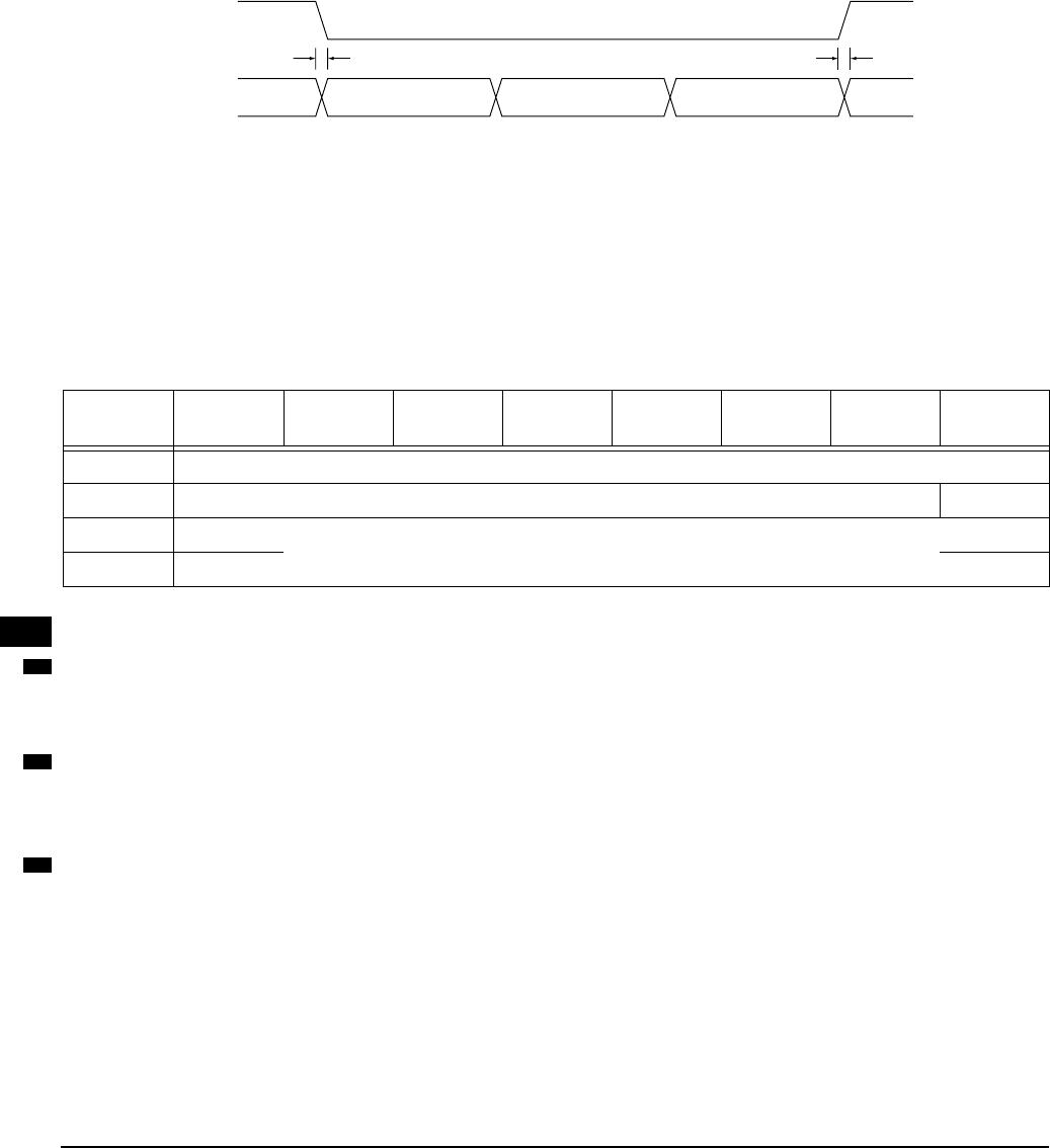
When the discover process determines 8067 mode is supported, the drive generates an ESI command to the
enclosure based on the SCSI Send Diagnostic or Receive Diagnostic Results command received from the
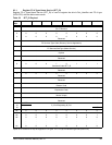
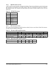
host. The format of the ESI command is shown in Table 57.
Field definitions (listed alphabetically)
Page Code
The Page Code is from the SCSI Send Diagnostic or Receive Diagnostic Results command diagnostic page that initiated
the ESI transfer.
Send
0 The ESI data transfer is from the enclosure to the drive.
1 The ESI data transfer is from the drive to the enclosure.
Send Diagnostic Parameter Length
For a Send Diagnostic command, the Send Diagnostic parameter length is the page length from the diagnostic page
header incremented by 4 to include the ESI command bytes, and reflects the total number of bytes that will be transferred
to the enclosure unless the transfer is truncated by a shorted allocation length in the CDB. The Send Diagnostic parameter
length is 0 for Receive Diagnostic Results commands.
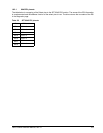
Table 57: ESI command format
Bit
Byte
76543210
0
Page Code
1 Reserved Send
2 (MSB) Send Diagnostic Parameter Length
3 (LSB)
1 µsec max 1 µsec max
-Parallel_ESI
SEL/ESI Bus
SEL_ID Discovery ESI Command Read or Write SEL_ID
Table
number
57
57
57


