


Appendix A-51
Appendix
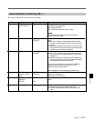
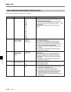
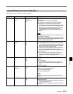
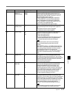
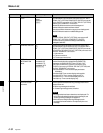
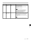
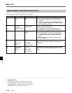
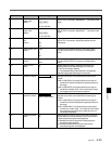
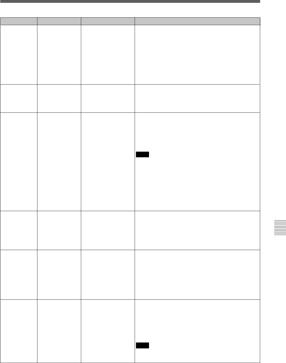
Item number Item FunctionSettable range
Specifies the signal output to the TIME CODE OUT
connector when the internal time code generator is in a
mode for regenerating the playback time code (i.e. during
auto edit mode or when item 607. is set to int-LTC or int-
VITC and item 606. is set to “regene”.)
off tape: The playback time code signal is output to the
TIME CODE OUT connector without regeneration.
regene: The playback time code signal is output to the
TIME CODE OUT connector after regeneration only
when the VTR is in playback mode.
through: The playback time code signal is output.
613 TC OUTPUT
SIGNAL IN
REGENE MODE
614 PHASE
CORRECTION
[off]
on
[off]
on
auto
TCG CF FLAG Specfies whether the color frame (CF) flag is set (ON) or
not set (OFF) in the blank bit of the time code data.
off: Color frame flag is set OFF.
on: Color frame flag is set ON.
auto: Color frame flag is set ON or OFF depending on the
phase relationship of the color framing between the
recorded video signal and the time code signal.
615
[offtape]
regene
through
Specifies whether the phase correction control of the LTC
signal generated by the time code generator is applied or
not.
off: The phase correction control is not applied.
on: The phase correction control is applied.
620 SUPERIMPOSED
CHARACTER
[off]
on
Specifies whether or not to superimpose time data and
operating status information on the signal output from the
MONITOR connector of HD SDI OUTPUT, the D CONV.
OUT (OPTION) COMPOSITE (SUPER) connector and the
3 (SUPER) connector of D CONV. SDI OUT (OPTION).
off: No information is superimposed.
on: Information is superimposed.
622 CHARACTER H-
POSITION
0
.
.
.
[8]
.
.
.
15
Sets the horizontal position of text information
superimposed on the signal output from the MONITOR
connector of HD SDI OUTPUT, the D CONV. OUT
(OPTION) COMPOSITE (SUPER) connector, the 3
(SUPER) connector of D CONV. SDI OUT (OPTION) and
the PULL DOWN OUT connectors. A setting of 0 displays
the information at the left edge of the screen, and the
position moves to the right as the setting is increased.
There are 16 possible settings, from 0 to 15.
623 CHARACTER V-
POSITION
0
.
.
.
[22]
.
.
.
23
Sets the vertical position of text information superimposed
on the signal output from the MONITOR connector of HD
SDI OUTPUT, the D CONV. OUT (OPTION) COMPOSITE
(SUPER) connector, the 3 (SUPER) connector of D CONV.
SDI OUT (OPTION) and the PULL DOWN OUT connectors.
A setting of 0 displays the information at the bottom of the
screen, and the position moves up as the setting is
increased. There are 24 possible settings, from 0 to 23.
Note
When this item is set to “auto”, the color frame flag is
determined by the operating mode of the time code
generator.
• When PRESET mode (i.e., item 606 is set to preset and
the VTR is in a mode other than automatic edit mode), the
time code signal is generated with color flame-locked to
the video signal, and the color frame flag is ON.
• When REGENE mode (i.e., item 606 is set to regene or
the VTR is in automatic edit mode), color frame flag is
OFF.
Note
If two-line display is selected in item 626., sometimes the
second line will disappear in the middle of the screen.