


— 11 —
KV-27S40 / 27S45 / 27S65 / 29SL40 / 29SL40A / 29SL40C/
29SL45 / 29SL65 / 29SL65C/ 29XL40M / 29XL40P / 29XT11A
10
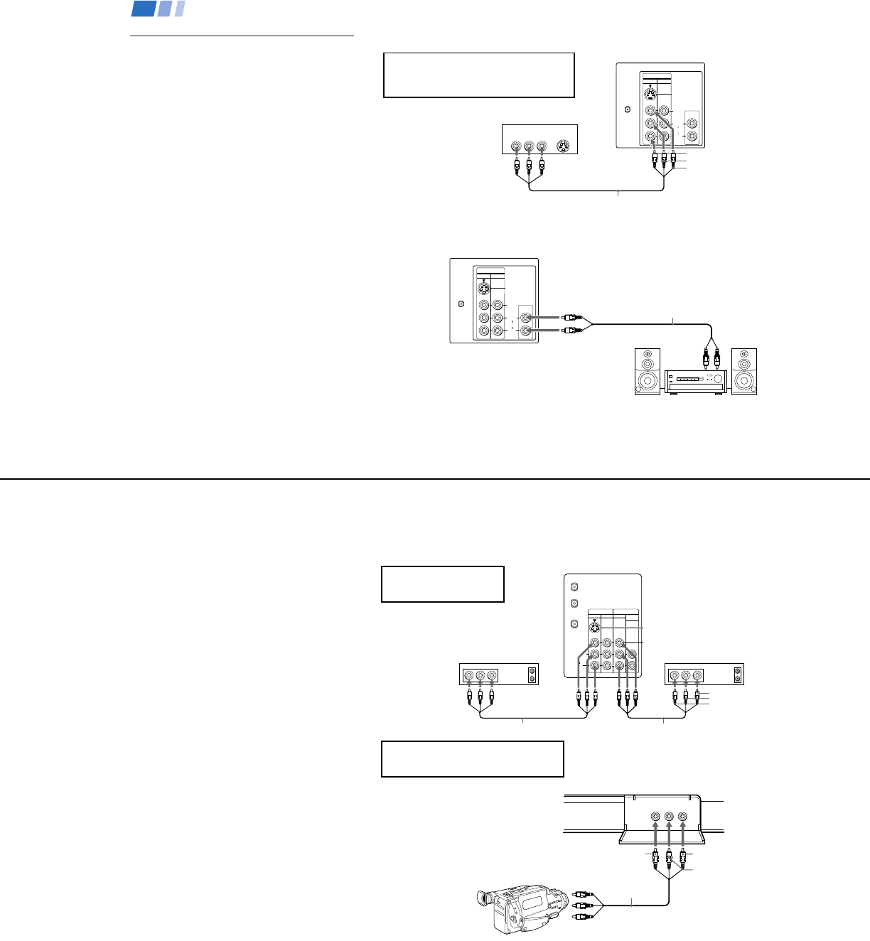
The following connections are for accessories
that will enhance your viewing options.
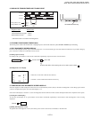
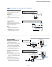
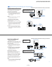
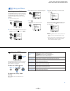
Connecting a DVD Player
AUDIO OUT
(
VAR/FIX
)
VIDEO
IN
12
VHF/UHF
S VIDEO
VIDEO
L
R
AUDIO
(
MONO
)
AUDIO R AUDIO L VIDEO
S VIDEO
LINE OUT
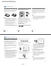
Additional Connections
VMC-810S/820S (not supplied)
AV outputs
1
(Rear of DVD player)
AUDIO-R (red)
AUDIO-L (white)
VIDEO (yellow)
Connecting and Installing the TV (continued)
AUDIO OUT
(
VAR/FIX
)
VIDEO
IN
12
VHF/UHF
S VIDEO
VIDEO
L
R
AUDIO
(
MONO
)
HRD
Line
input
AUDIO-R (red)
AUDIO-L (white)
RK-74A
(not supplied)
1
2
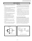
Disconnect all power sources before making any connections.
For optimum picture quality, use S VIDEO
instead of the yellow A/V cable. S Video
does not provide sound, your audio
connectors must still be connected.
Note
• For the best picture quality, connect the
DVD player directly to the TV.
(Rear of TV)
(Rear of TV)
1
Using A/V connectors, connect LINE OUT
on your DVD to VIDEO IN on your TV
(Red-AUDIO Right, White-AUDIO Left,
Yellow-VIDEO).
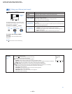
Connecting an audio system
For enhanced sound, connect your audio
system to your TV.
1
Using AUDIO connectors, connect AUDIO
OUT on your TV to one of the unused line
inputs (e.g. TV, AUX, TAPE 2) on your
stereo (White-AUDIO Left, Red-AUDIO
Right).
2
Set your stereo to the chosen line input
(e.g. TV, AUX, TAPE 2). Refer to page 20
of this manual for additional audio setup
instructions.
11
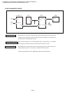
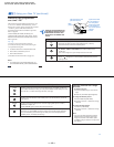
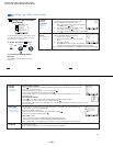
If you have an S Video equipped
camcorder, you can use an S Video
connection for optimum picture quality.
IN
VIDEO 1
VHF/UHF
L
R
AUDIO
(
MONO
)
VIDEO 3 MONITOR
AUDIO
(VAR/FIX)
OUT
TO
CONVERTER
AUX
S VIDEO
VIDEO
LINE
OUT
OUT
IN
LINE
IN
OUT
IN
AUDIO R AUDIO L VIDEO AUDIO R AUDIO L VIDEO
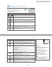
Disconnect all power sources before making any connections.
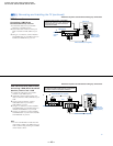
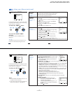
Connecting two VCRs for tape
editing using MONITOR OUT
VCR (for playback)
VCR (for recording)
VMC-810S/820S (not supplied)
VMC-810S/820S (not supplied)
(Rear of KV-27V65)
VIDEO (yellow)
AUDIO-L (white)
AUDIO-R (red)
1
2
You cannot change video
inputs while editing using
MONITOR OUT.
VIDEO 2 INPUT
L
(
MONO
)
-
AUDIO
-RVIDEO
VIDEO 2 INPUT
VIDEO
L
(
MONO
)
-
AUDIO
-
R
AUDIO-L (white)
AUDIO-R (red)
VIDEO (yellow)
AV output
VMC-810S/820S
(not supplied)
(Front of KV-27V40, 27V45, 27V65 only)
• KV-27V40, 27V45, 27V65 only
MONITOR OUT gives you the ability to use a
second VCR to record a program being played
by the primary VCR or to perform tape
editing and dubbing.
1
Connect the VCR intended for playback
using the setup instructions on page 7 of
this manual.
2
Using A/V connectors, connect AUDIO
and VIDEO IN on your VCR intended for
recording to MONITOR AUDIO and
VIDEO OUT on your TV.
Connecting a camcorder
This connection is convenient for viewing a
picture directly from your camcorder.
Using A/V connectors, connect AUDIO and
VIDEO OUT on your camcorder to AUDIO
and VIDEO IN on your TV (Yellow-VIDEO,
White-AUDIO Left, Red-AUDIO Right).
Connection can also be made directly to your
A/V input located on the rear of your TV.
Note
•
If you are connecting a monaural camcorder,
connect only the single white audio output
to the left input on your TV.