


— 4 —
KV-27S40 / 27S45 / 27S65 / 29SL40 / 29SL40A / 29SL40C/
29SL45 / 29SL65 / 29SL65C/ 29XL40M / 29XL40P / 29XT11A
CAUTION!
SHORT CIRCUIT THE ANODE OF THE PICTURE TUBE AND
THE ANODE CAP TO THE METAL CHASSIS, CRT SHIELD,
OR CARBON PAINTED ON THE CRT, AFTER REMOVING
THE ANODE.
WARNING!!
AN ISOLATION TRANSFORMER SHOULD BE USED
DURING ANY SERVICE TO AVOID POSSIBLE SHOCK
HAZARD, BECAUSE OF LIVE CHASSIS.THE CHASSIS OF
THIS RECEIVER IS DIRECTLY CONNECTED TO THE AC
POWER LINE.
SAFETY-RELATED COMPONENT WARNING!!
COMPONENTS IDENTIFIED BY SHADING AND MARK
¡ ON THE SCHEMATIC DIAGRAMS, EXPLODED VIEWS
AND IN THE PARTS LIST ARE CRITICAL FOR SAFE
OPERATION. REPLACE THESE COMPONENTS WITH
SONY PARTS WHOSE PART NUMBERS APPEAR AS
SHOWN IN THIS MANUAL OR IN SUPPLEMENTS
PUBLISHED BY SONY. CIRCUIT ADJUSTMENTS THAT
ARE CRITICAL FOR SAFE OPERATION ARE IDENTIFIED
IN THIS MANUAL. FOLLOW THESE PROCEDURES
WHENEVER CRITICAL COMPONENTS ARE REPLACED
OR IMPROPER OPERATION IS SUSPECTED.
ATTENTION
APRES AVOIR DECONNECTE LE CAP DE L'ANODE, COURT-CIRCUITER
L'ANODE DU TUBE CATHODIQUE ET CELUI DE L'ANODE DU CAP AU
CHASSIS METALLIQUE DE L'APPAREIL, OU AU COUCHE DE CARBONE
PEINTE SUR LE TUBE CATHODIQUE OU AU BLINDAGE DU TUBE
CATHODIQUE.
ATTENTION!!
AFIN D'EVITER TOUT RESQUE D'ELECTROCUTION PROVENANT D'UN
CHÁSSIS SOUS TENSION, UN TRANSFORMATEUR D'ISOLEMENT DOIT
ETRE UTILISÉ LORS DE TOUT DÉPANNAGE. LE CHÁSSIS DE CE
RÉCEPTEUR EST DIRECTEMENT RACCORDÉ À L'ALIMENTATION
SECTEUR.
ATTENTION AUX COMPOSANTS RELATIFS A LA SECURITE!!
LES COMPOSANTS IDENTIFIES PAR UNE TRAME ET PAR UNE MARQUE
¡ SUR LES SCHEMAS DE PRINCIPE, LES VUES EXPLOSEES ET LES
LISTES DE PIECES SONT D'UNEIMPORTANCE CRITIQUE POUR LA
SECURITE DU FONCTIONNEMENT. NE LES REMPLACER QUE PAR DES
COMPOSANTS SONY DONT LE NUMERO DE PIECE EST INDIQUE DANS
LE PRESENT MANUEL OU DANS DES SUPPLEMENTS PUBLIES PAR
SONY. LES REGLAGES DE CIRCUIT DONT L'IMPORTANCE EST CRITIQUE
POUR LA SECURITE DU FONCTIONNEMENT SONT IDENTIFIES DANS
LE PRESENT MANUEL. SUIVRE CES PROCEDURES LORS DE CHAQUE
REMPLACEMENT DE COMPOSANTS CRITIQUES, OU LORSQU'UN
MAUVAIS FONTIONNEMENT SUSPECTE.
WARNINGS AND CAUTIONS
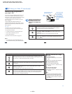
SELF-DIAGNOSTIC FUNCTION
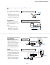
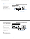
The units in this manual contain a self-diagnostic function. If an error occurs, the STANDBY/TIMER lamp will automatically begin to
flash. The number of times the lamp flashes translates to a probable source of the problem. A definition of the STANDBY/TIMER lamp
flash indicators is listed in the instruction manual for the user's knowledge and reference. If an error symptom cannot be reproduced, the
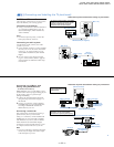
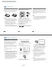
remote commander can be used to review the failure occurrence data stored in memory to reveal past problems and how often these
problems occur.
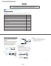
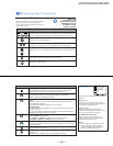
1. DIAGNOSTIC TEST INDICATORS
When an error occurs, the STANDBY/TIMER lamp will flash a set number of times to indicate the possible cause of the problem. If there
is more than one error, the lamp will identify the first of the problem areas.
Results for all of the following diagnostic items are displayed on screen. No error has occured if the the screen displays a "0" .
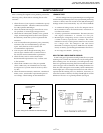
Note 1: If a +B overcurrent is detected, stoppage of the vertical deflection is detected simultaneously.
The symptom that is diagnosed first by the microcontroller is displayed on the screen.
Note 2: Refer to Screen (G2) Adjustment in Section 3-4 of this manual.
Diagnostic Item No. of times Self-dia
g
nostic dis
p
la
y
/ Probable Cause Detected S
y
m
p
toms
Description STANDBY/TIMER Dia
g
nostic result Location
lamp flashes
* Power does not turn on Does not li
g
ht * Power cord is not plu
gg
ed in. * Power does not come on.
* Fuse is burned out
(
F5050
)
(
E Board
)
* No power is suppled to the TV.
* AC power suppl
y
is fault
y
.
* +B overcurrent
(
OCP
)
2 times 2:0 or 2:1 * H.OUT
(
Q502
)
is shorted.
(
A board
)
* Power does not come on.
* IC1751 and Q1751 is shorted.
(
C board
)
* Load on power line is shorted.
* Vertical deflection stopped 4 times 4:0 or 4:1 * +13V is not supplied.
(
A board
)
* Has entered standb
y
state after horizontal raster.
* IC 541 is fault
y
(
A board
)
* Vertical deflection pulse is stopped.
* Power line is shorted or power suppl
y
is stopped.
* White balance failure 5 times 5:0 or 5:1 * Video OUT
(
Q306 to 308
)
is fault
y
.
(
A board
)
* No raster is
g
enerated.
(
not balanced
)
* IC301 is fault
y
.
(
A board
)
* CRT cathode current detection reference pulse
* G2 is improperl
y
ad
j
usted.
(
Note 2
)
output is small.