


— 3 —
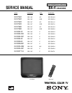
KV-27S40 / 27S45 / 27S65 / 29SL40 / 29SL40A / 29SL40C/
29SL45 / 29SL65 / 29SL65C/ 29XL40M / 29XL40P / 29XT11A
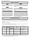
Warnings and Caution ..................................................... 4
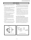
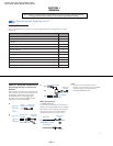
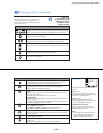
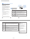
Self-Diagnostic Function ................................................ 4
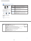
Safety Check Out Instructions ........................................ 7
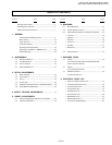
1. GENERAL
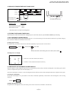
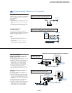
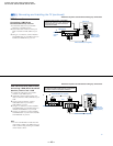
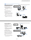
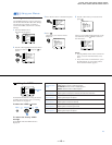
Connecting and Installing the TV ............................. 8
Basic Set Up .............................................................. 12
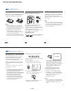
Using Your TV.............................................................12
Using Your Menus.......................................................15
Operating Video Equipment....................................... 19
Operating a Cable Box or DBS Receiver....................20
Troubleshooting.......................................................... 20
2. DISASSEMBLY
2-1. Rear Cover Removal .....................................................22
2-2. A Board Removal ..................................................... 22
2-3. Service Position ........................................................ 22
2-4. Picture Tube Removal ................................................... 23
3. SET-UP ADJUSTMENTS
3-1. Beam Landing............................................................. 24
3-2. Convergence............................................................... 25
3-3. Focus........................................................................... 26
3-4. Screen (G2)................................................................. 26
3-5. Method of Setting the Service Adjustment Mode....... 26
3-6. White Balance Adjustments........................................ 26
4. SAFETY RELATED ADJUSTMENTS......................... 27
5. CIRCUIT ADJUSTMENTS
5-1. Electrical Adjustment by Remote Commander........... 29
5-2. A Board Adjustments.................................................. 32
TABLE OF CONTENTS
Section Title PageSection Title Page
6. DIAGRAMS
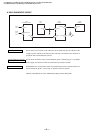
6-1. Block Diagrams.......................................................... 35
6-2. Circuit Boards Location.............................................. 38
6-3. Printed Wiring Boards and Schematic Diagrams .......38
• A Board...................................................................... 39
• P Board....................................................................... 47
• K Board ..................................................................... 49
• C Board...................................................................... 50
• E Board ...................................................................... 51
• HZ Board.................................................................... 52
6-4. Semiconductors........................................................... 53
7. EXPLODED VlEWS
7-1. Chassis ..........................................................................54
(KV-27S40/27S45/29SL40/29SL45/29XL40M/29XL40P/
29XT11A/29SL40A/29SL40C)
7-2 . Chassis..........................................................................55
(KV-27S65/29SL65/29SL65C)
7-3. Main Power Switch...................................................... 56
(KV-29SL40A/29XT11A)
8. ELECTRICAL PARTS LIST
• Table of Contents for Parts List...................................57
• A Board Common Parts List....................................... 59
• A Board Variant Lists.................................................. 68
• C Board Parts List....................................................... 79
• E Board Parts List....................................................... 79
• K Board Parts List.......................................................80
• P Board Parts List....................................................... 81
• HZ Board Parts List.....................................................82
• Accessories and Packaging........................................ 82