


7
US
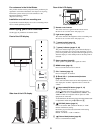
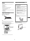
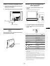
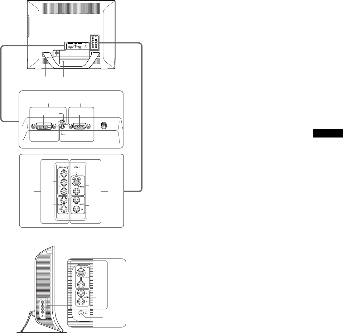
L Connector cover (page 9)
Remove this cover when you connect cables or cords.
M Screw positions of VESA compatible mounting arm
or stand (page 9)
Attach the VESA compatible mounting arm or stand.
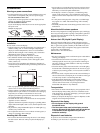
Rear of the LCD display
Side view of the LCD display
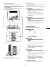
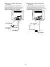
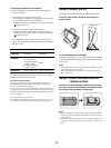
N AC IN connector (page 13)
This connector connects the power cord (supplied).
O Security Lock Hole
The security lock hole should be used with the Kensington
Micro Saver Security System.
Micro Saver Security System is a trademark of Kensington.
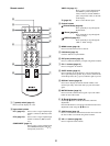
P PC 1 connectors
1 DVI-D input connector (digital RGB) for PC 1
(page 10)
This connector inputs digital RGB video signals that
comply with DVI Rev.1.0.
2 Audio input jack for PC 1 (page 10)
This jack inputs audio signals when connected to the
audio output jack of a computer or other equipment
connected to PC 1.
Q PC 2 connectors
1 HD15 input connector (analog RGB) for PC 2
(page 10)
This connector inputs analog RGB video signals (0.700
Vp-p, positive) and sync signals.
2 Audio input jack for PC 2 (page 10)
This jack inputs audio signals when connected to the
audio output jack of a computer or other equipment
connected to PC 2.
R VHF/UHF jack (page 12)
This jack inputs a signal from an antenna.
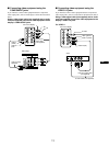
S COMPONENT jacks
1 Y/P
B
/P
R
Component Video input jacks for
COMPONENT (page 11)
These jacks input Y/P
B
/P
R
Component Video signals (Y/
B-Y/R-Y or Y/P
B
/P
R
).
2 Audio input jacks for COMPONENT (page 11)
These jacks input audio signals when connected to the
audio output jacks of a DVD player or other equipment
connected to COMPONENT.
T VIDEO 1 jacks
1 Composite/S video input jacks for VIDEO 1
(page 11)
These jacks input composite video or S video signals.
When you connect video equipment to both composite
video input and S video input jacks, the signal from the S
video jack is displayed.
2 Audio input jacks for VIDEO 1 (page 11)
These jacks input audio signals when connected to the
audio output jacks of a VCR or other equipment
connected to VIDEO 1.
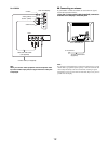
U VIDEO 2 jacks
1 Composite/S video input jacks for VIDEO 2
(page 11)
These jacks input composite video or S video signals.
When you connect video equipment to both composite
video input and S video input jacks, the signal from the S
video jack is displayed.
2 Audio input jacks for VIDEO 2 (page 11)
These jacks input audio signals when connected to the
audio output jacks of a VCR or other equipment
connected to VIDEO 2.
V Headphones jack (page 35)
This jack outputs audio signals to the headphones.
PC 1 PC 2 VHF/UHF
qf
qg
qh qj
qk
w;ql
1
2
1
2
1
2
1
2
wa
ws
1
2