9
US
Setup
Before using your display, check that the following items are
included in your carton:
•LCD display
• Remote control
• Size AAA batteries (2)
• Power cord
• HD15-HD15 video signal cable (analog RGB)
• DVI-D video signal cable (digital RGB)
• Audio cord (stereo miniplug)
• 75-ohm coaxial cable
• CD-ROM (utility software for Windows/Macintosh, Operating
Instructions, etc.)
• Warranty card
• Quick Setup Guide
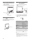
Setup 1:Open the stand
Note
The stand is folded at the factory. Be sure not to place the display
vertically with the stand as it is. Otherwise, the display may topple over.
Setup 2:Connect the cables
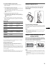
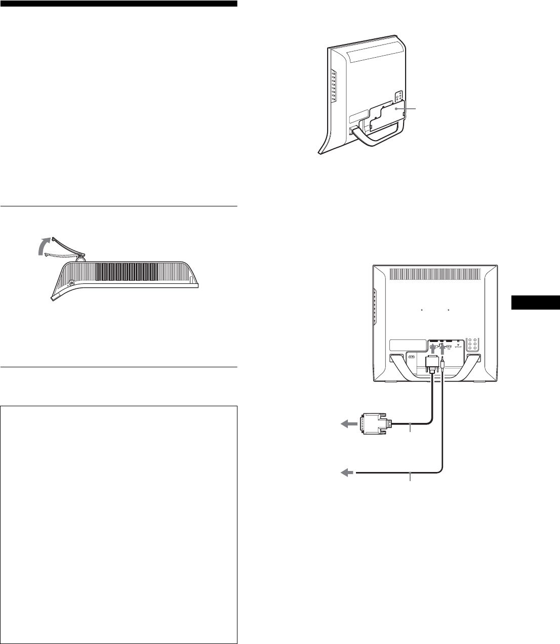
Remove the connector cover.
Push the hooks and draw the connector cover towards you.
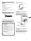
x Connecting a computer using the PC 1
connectors
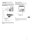
If you intend to connect a computer equipped with a DVI
connector (digital RGB), follow the instructions below.
Using the supplied DVI-D video signal cable (digital
RGB) and the supplied audio cord, connect the
computer to the display’s PC 1 connectors.
x Connecting a computer using the PC 2
connectors
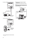
If you intend to connect a computer equipped with an HD15
connector (analog RGB), follow the instructions below.
Using the supplied HD15-HD15 video signal cable
(analog RGB) and the supplied audio cord, connect the
computer to the display’s PC 2 connectors.
Connect the computer according to the following illustrations.
• Turn off the display, computer, and other equipment
before connecting them.
• If you intend to connect:
– A computer equipped with an HD15 output connector
(analog RGB)
t See “Connecting a computer using the PC 2
connectors” on this page.
– Video equipment that has component video output
jacks
t See “Connecting video equipment using the
VIDEO 1 jacks” (page 10).
– Video equipment that has composite/S video output
jacks
t See “Connecting video equipment using the
VIDEO 2 jacks” (page 11).
–An antenna
t See “Connecting an antenna” (page 11).
Note
Do not touch the pins of the video signal cable connector as this might
bend the pins.
connector cover
to the computer’s DVI output
connector (digital RGB)
to the DVI-D
input
DVI-D video signal
cable (digital RGB)
(supplied)
to the
audio input
for PC 1
to the audio output
of the computer
audio cord (supplied)


