


Section 3.2 - Connections (parallel units)
3-2
the lowest ID. Refer to the units’ manuals for full
details of setting the ID.
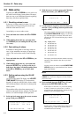
3.2 Connections (parallel
units)
The RC-898 allows transport control of a unit con-
nected to the
EXT 1
parallel port. Before making
this connection, check the specifications of the
other unit to ensure that the control pins available
match those provided by the RC-898, as shown
below in 3.2.2, “Parallel control/GPI pinout”.
If a passive unit that does not supply power to the
tally supply pin (8) is being used, switch 1
(
TALLY POWER
) of the RC-898 [45] must be set
on (down) to allow the RC-898 to provide this
power.
3.2.1 Connections (GPI event units)
The
EXT 1
parallel port may also be used for the
purpose of controlling up to five GPI event-con-
trolled devices.
The way in which these devices may be triggered
from the RC-898 is explained in 9.2, “Controlling
GPI devices”.
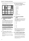
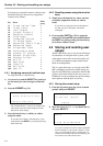
3.2.2 Parallel control/GPI pinout
The following table gives the pin assignments for
the parallel/GPI connector (
EXT 1
). GPI connec-
tions are shown in square brackets:
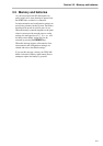
3.3 Connections (RS-422
units)
The RC-898 allows control of a unit implementing
the Sony P2 protocol. This connection is made
through the
EXT 2
serial port [43], using a serial
cable designed for this purpose. The pinout for
this connector is as follows:
Make the connection using a cable designed for
RS-422 connection (check the pinout of your P2
device before making the connection). This
machine may now be controlled by the RC-898
when the
E2 MACHINE
indicator [8] is lit.
3.4 A note on system clocks
When working with many digital audio units, all
these units must be fed from the same clock
source (either word or video). If this is not done,
there is a risk that speakers, etc. may be damaged.
Note that this clock master is entirely different
from the timecode master in a studio setup. It is
perfectly possible for a clock slave to be a time-
code master and vice versa.
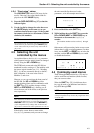
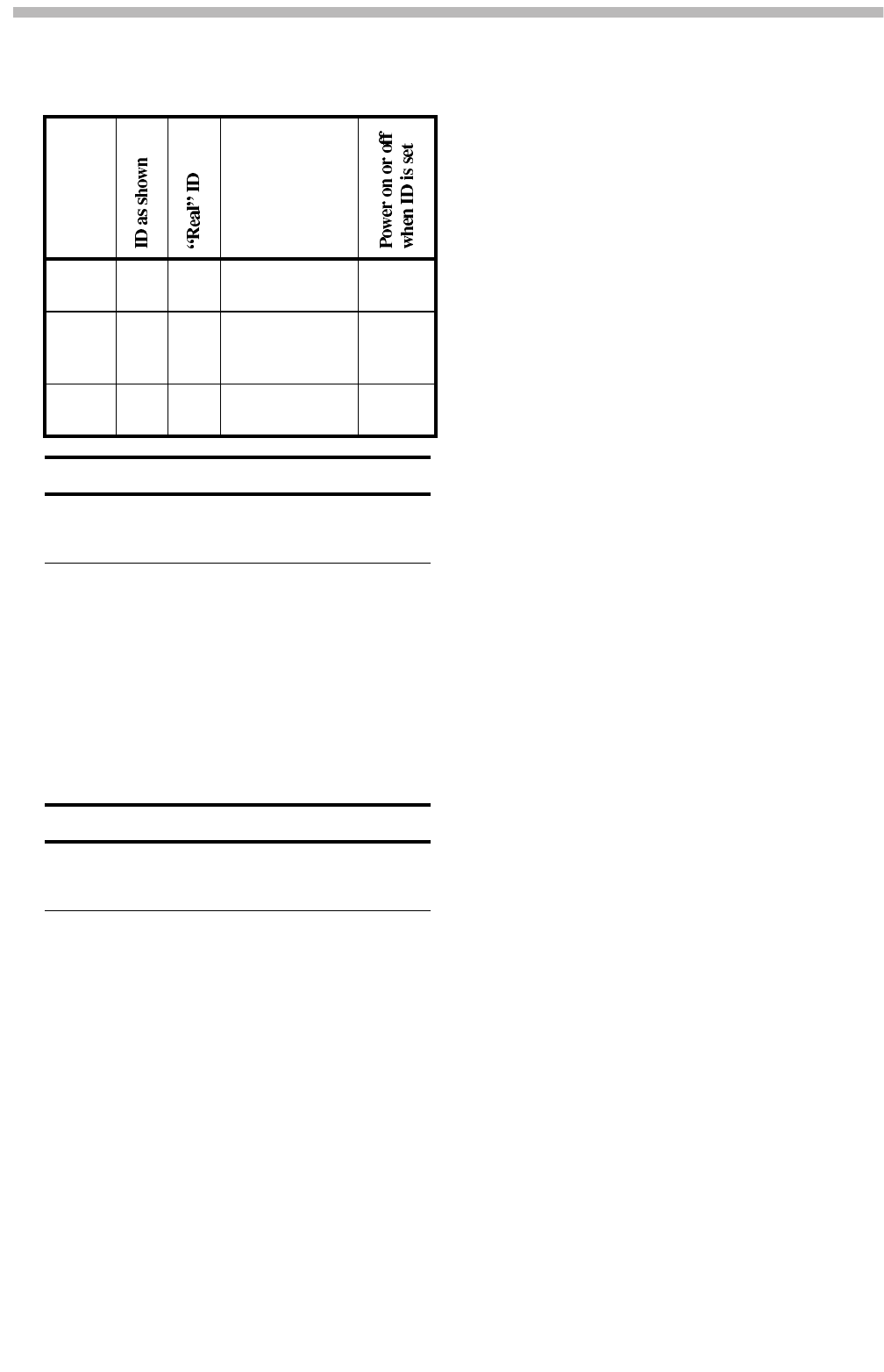
Unit
How the ID is
set (see the
unit’s manual
for details)
DA-98 1 1 Menu system (see
9.2)
ON
DA-88 0 1 Rotary switch on
rear panel (see p23–
24)
OFF
DA-38 1 1 Tape counter menu
system (see 7-2)
ON
NOTE
When you set the machine IDs, you can set the ID of any
machine first, but we recommend doing this in a standard
sequence, working from the head of the chain to the tail.
NOTE
The RC-898 provides only transport control for a unit con-
nected to the parallel port. Functions such as track arming,
etc. are not possible when using the
EXT 1
parallel port.
1
STOP/[Event 1]
2
PLAY/[Event 2]
3
FF/[Event 3]
4
REW/[Event 4]
5
REC/[Event 5]
6
N/C
7
Common
8
Tally supply
9
PLAY tally
10
FF tally
11
REW tally
12
STOP tally
13
REC tally
14
REC COMMAND tally
15
GND
1
Shield
2
RX+
3
TX–
4
GND
5
—
6
GND
7
RX–
8
TX+
9
Shield