


Section 9.1 - Controlling the parallel port device
9-1
9 – External control and
settings
This section covers the control of DTRS and other
units.
9.1 Controlling the parallel
port device
When a unit is connected to the
EXT 1
port [42]
of the RC-898, the transport may be controlled
usig the RC-898 transport controls. The pinouts
for these transport controls are given in 3.2.2,
“Parallel control/GPI pinout”.
To select the “parallel” unit for control:
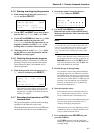
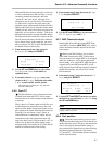
1) Press the
MACHINE
key [31].
The
LOCATE TIME/VALUE
display will show
SELECT
.
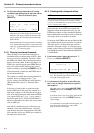
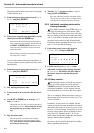
2) Press
7
on the numeric keypad.
The
E1
indicator on the machine number indica-
tors [8] will light, showing that the parallel port
unit is now selected for control.
9.2 Controlling GPI devices
Up to five GPI devices may be connected to the
EXT 1
port. These devices may be triggered at set
times, based on the times received for display on
the
TAPE TIME
display of the RC-898.
Refer to the documentation supplied with any
units to be controlled by GPI to find out whether
the unit requires the controlling circuit to be
closed or open in order to trigger the event, and
the time of the pulse needed to act as a trigger.
The wiring for the parallel port when used with
GPI devices is given in 3.2.2, “Parallel control/
GPI pinout”.
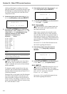
9.2.1 Setting up GPI devices
The polarity of the GPI devices, and the pulse
width necessary to trigger an event, may be set up
individually for each GPI device.
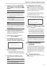
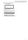
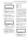
1) From menu group 1, move the cursor to
GPI
Setup and press
SELECT
:
2) Holding down the
SHIFT
key, use the
NEXT
(
UP
) and
PREVIOUS
(
DOWN
) keys to select
the required GPI unit.
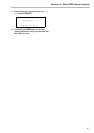
3) Move the cursor to the
Pol (polarity) field,
and use the
UP
and
DOWN
keys to select either
open or close for the polarity of the unit’s
event trigger.
When
open
is selected, the event is triggered
when the circuit is open (i.e. it is a “push-to-
break”-type circuit. When
close
is selected,
the event is triggered when the circuit is closed
(i.e.it is a “push-to-make”-type circuit).
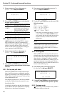
4) Move the cursor to the Width field and use
the
UP
and
DOWN
keys to select the pulse
width of the event trigger.
The minimum value for the pulse width is 0 ms,
and the maximum is 990 ms, settable in 10ms
increments.
Most GPI units require a trigger width of 200 ms.
If you are unsure of the trigger width for a particu-
lar device, we suggest that you try this value first
of all.
9.2.2 Setting the trigger points
The location memories also serve as GPI trigger
points, when GPI devices are connected to the
EXT 1
port.
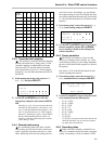
Since up to 10 GPI events can be associated with
location memories, we suggest the following
method of working:
• Use a “block” of location memories for this
purpose, starting at a number such as 80 or 90.
NOTE
The RC-898 provides only transport control for a unit con-
nected to the parallel port. Functions such as track arming,
etc. are not possible when using the
EXT 1
parallel port.
NOTE
Since the GPI event timings are based on the information
transmitted from the DTRS recorders connected to the RC-
898, the timing may “slip” by up to one frame.
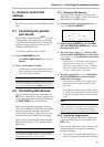
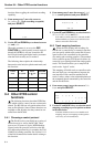
GPI Setup
GPI 1
Pol Width
open 010 mS
NOTE
Note that the polarity setting here is also used as the polarity
setting for transport control signals sent to the E1 parallel
port device (
see 9.1, “Controlling the parallel port
device”
. In this case, the pulse width is fixed at 500 ms.)