7
Introduction
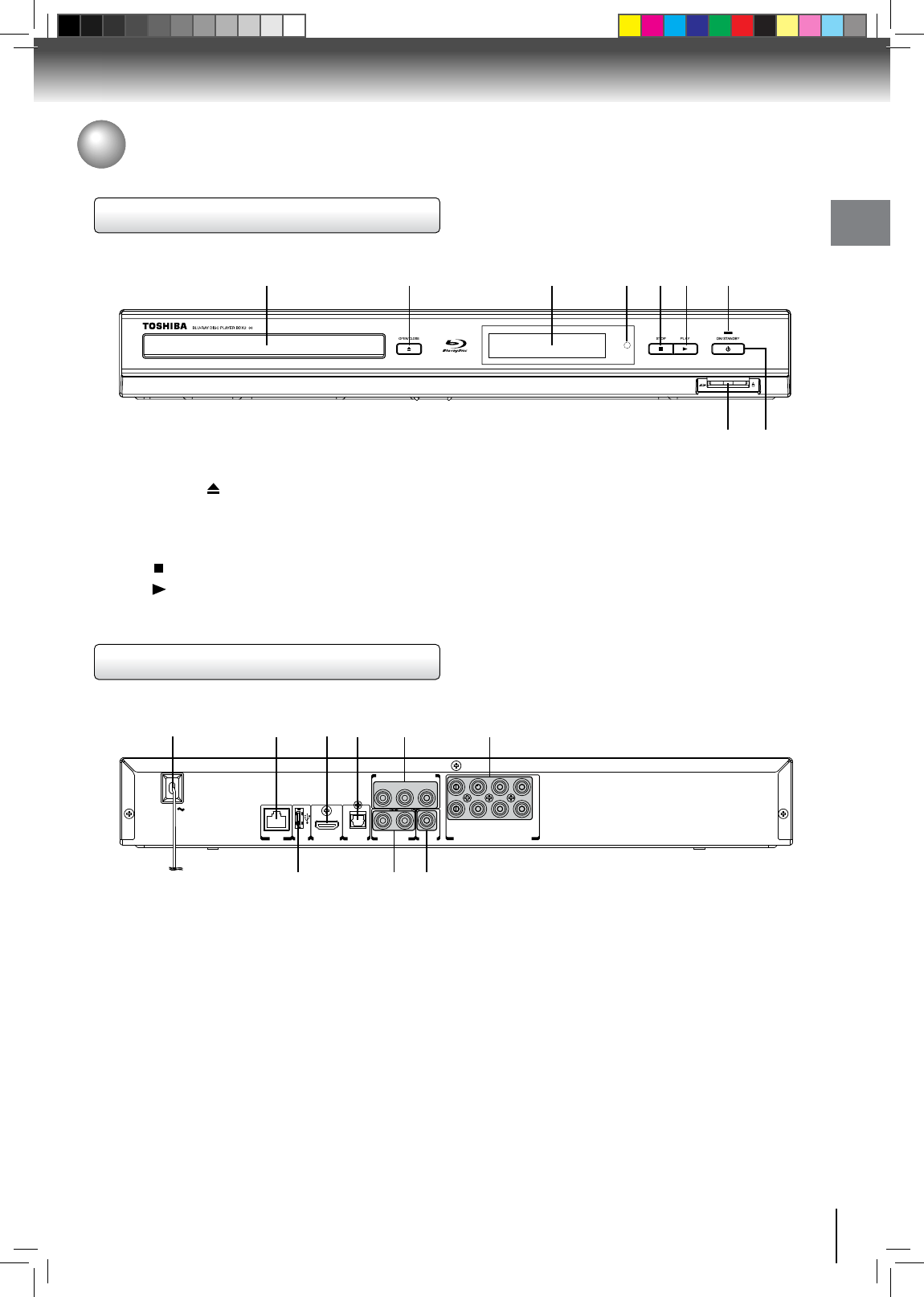
Front panel
Rear panel
1 2 3 4 5 6
7 8 9
AC IN
LAN
MULTI CHANNEL AUDIO OUTPUT
R
AUDIO OUT
L
VIDEO
OUTPUT
USB
HDMI OUT
BITSTREAM / PCM
OPTICAL
Y PB PR
SBL
C SL FL
SBR
SW SR FR
COMPONENT VIDEO OUT
1 2 3 4 5 6 7
89
5
1. Disc tray
2. OPEN/CLOSE
button
3. Display
•Referto“FrontPanelDisplay”onpage10.
4. Remote sensor
5. STOP
button
6. PLAY
button
1. AC power cord
•ConnecttoastandardACoutlettosupplypowertothis
unit.
•UnplugthiscordfromtheACoutlettocompletelyturn
off the unit.
2. LAN terminal
•UsetoconnectanetworkequipmentwithLANcable.
3. HDMI OUT jack
•UsetoconnectaTVwithanHDMIcompatibleportvia
an HDMI cable.
4. OPTICAL jack
•UsetoconnectanAVreceiver/amplier,DolbyDigital/
DTS decoder or other device with a digital audio optical
input jack using a digital audio optical cable.
7. ON/STANDBY indicator
8. SD card slot
9. ON/STANDBY button
•Presstoturnon theunit,ortoturntheunitintothe
standby mode. (To completely turn off the unit, you must
unplug the AC power cord.)
5. COMPONENT VIDEO OUT jacks
•UsetoconnectaTVwithcomponentvideoinputsusing
a component video cable.
6. MULTI CHANNEL AUDIO OUTPUT jacks
•UsetoconnectanAVreceiver/amplierwithaaudio
cable.
7. USB jack
•UsetoconnectUSBashdrives(notincluded).
8. AUDIO OUT jacks
•UsetoconnectaTV,anAVreceiver/amplierorother
device with a composite audio cable.
9. VIDEO OUT jack
•UsetoconnectaTV,anAVreceiverorotherdevicewith
a composite video cable.


