


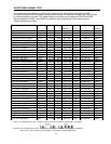

16
XGA50 1024 x 768 160
1024
24 136
1344
40.30
50.0 54.163
29 768
3
6
806
XGA60 1024 x 768 160
1024
24 136
1344
48.363
60.004
65
29 768
3
6
806
XGA70 1024 x 768
144
1024
24 136
1328
56.476
70.069 75
29 768
3
6
806
XGA75 1024 x 768 176
1024
16 96
1312
60.023
75.029 78.75
28 768
1
3
800
XGA85 1024 x 768 208
1024
48 96
1376
68.677
84.997 94.5
36 768
1
3
808
MAC19
1024 x 768 172
1024
34 96
1328
60.135
74.7 79.86
30 768
4
3
805
SXGA5
0
1280 x 1024
248
1280
48 112
1688
53.30
50.0 89.97
38 1024
1
3
1066
SXGA6
0 1280 x 1024
248
1280
48 112
1688
63.981
60.02
108
38 1024
1
3
1066
SXGA7
5 1280 x 1024
248
1280
16 144
1688
79.976
75.025 135
38 1024
1
3
1066
SEGA6
0
640 x 480
87
640 43 82
852 31.678
59.770 26.990
33 480
14
3
530
15.78 430 x 252
46
430 10 33
519 15.780
60.692 8.190
2 252
2
4
260
Tri-F60 640 x 480 116 640 38 64
858 31.469
59.941 27.000
30 480
9
6
525
480p 720 x 480
56
720 16 64
856 31.542
60.080 27.000
30 480
9
6
525
720p 1280 x 720 270
1024
260 96
1650
45.000
60.000 74.250
20 720
5
5
750
EDTV 720 x 480
59
720 16 63
858 31.469
59.941 27.000
33 480
6
6
525
Note 1: The clock pulse is made in projection unit automatically. External clock input is not equipped.
Note 2: When 15kHz NTSC/PAL signal is supplied to the RGB input terminal, the Digital Signal Link function is not guaranteed for correct
signal transfer.
Note 3: When signal except standard type (for example, played back software with a copy guard or a special effect play of VCR, etc.) is
supplied to the RGB input terminal, projection unit may not function properly.
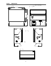
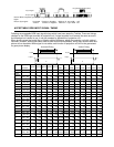
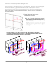
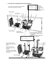
CONNECTION AT A MULTI PROJECTION SYSTEM
A C ? ?
R G B? ? -1
RG B? ? -2
? ? ? ? ? ?? ? ?
Unit-4 Unit-3
Unit-1
Unit-2
OUT IN RGB 2 RGB 1DIGITAL SIGNAL LINK RGB INPUT
CONTROL RS-232C INOUTPOWER FAN LAMP REMOTE
OUT IN RGB 2 RGB 1DIGITAL SIGNAL LINK RGB INPUT
CONTROL RS-232C INOUTPOWER FAN LAMP REMOTE
OUT IN RGB 2 RGB 1DIGITAL SIGNAL LINK RGB INPUT
CONTROL RS-232C INOUTPOWER FAN LAMP REMOTE
OUT IN RGB 2 RGB 1
DIGITAL SIGNAL LINK RGB INPUT
CONTROL RS-232C INOUTPOWER FAN LAMP REMOTE
A C ? ?
A C
? ?
A C
? ?
VIDEOOUT IN VIDEOOUT IN
VIDEOOUT IN
VIDEO
OUT IN
? ? ? ? ?
AC INLET
AC OUTLET
15A 125V/250V AC
AC100V-240V 50/60Hz
UNSWITCHED MAX 10A
AC INLET
AC OUTLET
15A 125V/250V AC
AC100V-240V 50/60Hz
UNSWITCHED MAX 10A
AC INLET
AC OUTLET
15A 125V/250V AC
AC100V-240V 50/60Hz
UNSWITCHED MAX 10A
AC INLET
AC OUTLET
15A 125V/250V AC
AC100V-240V 50/60Hz
UNSWITCHED MAX 10A
MULTIPLE CONNECTION
Wired remote control
RGB-1 signal
RGB
-
2 signal
Video signal
RS232C link
Digital Link
AC power source
This can be also possible to link up to 4 sets
by separately purchasing 6ft monitor power
interconnect cable
AC power
AC power
This is one of the example of connection
for a multi-projection system using four
projection units.
In this example, signal sources are
supplied from composite video signal to
video-card and signal from a PC is
connected to each cubes by signal links.
The optional wired remote controller is
connected to Unit-1 and all the units
could be controlled by the remote
control through System Bus-Link when
RS232C communication links are daisy
chain connected.
The final RS232C output should not
return to 1
st
cube.
When both, RS232C control signal and
CT-90000 wired remote control are
connected, the remote control has a
priority over PC, RS-232C connection
thus PC control is not possible.