


28
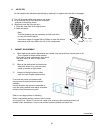
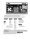
3-2. Adjust Mode
Press ADJUST to enter Adjust Mode.
To exit Adjust Mode press ADJUST twice (one press will request confirmation that
you wish to exit Adjust Mode).
3-3. Saving adjustments
Adjusted value will be memorized into its non-volatile memory when WRITE button is clicked.
In case if the new adjustment value is not acceptable, simply shut off the power by rocker switch
so that this new adjusted value will be erased and go back to “before adjustment” value.
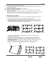
3-4. Adjustment parameters
All parameters except ‘Layout’ can be adjusted using the ? ? ? ? buttons.
‘Layout’ position is adjusted using the ´ ` < > buttons.
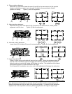
3-5. Internal Test Pattern
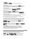
Test Patterns can be accessed by pressing TEST.P in Adjust Mode.
Continuously pressing TEST.P button will cycle through the available patterns or individual
patterns can be selected by entering the relevant two digits number as 0 7 TEST.P for direct
number access for test signal #7.
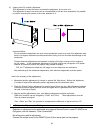
3-6. White Balance adjustment
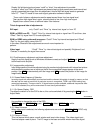
There are three independent memories for white balance adjustments, press WB in NORMAL mode
to select the desired memory (WB1, WB2 or WB3) before making adjustments.
There are two stages for white balance or color balance adjustment to allow adjustment of
low-signal-level and high-signal-level portions of the image.
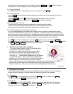
For low-signal level adjustment, 10-20% IRE signal is required and this should be provided by
the signal source to be used (i.e. if video is the source, a video test pattern generator should be
used and if computer is the main source, test pattern generating software should be used).
BRIGHTNESS will control the overall brightness of the image and CUTOFF then followed by
ADJ.R, ADJ.G and ADJ.B can be used to adjust the relative intensities of red, green and
blue.
For high-signal level adjustment, around 70-80-90% IRE signal is required.
CONTRAST will control the overall level of the image and DRIVE followed by ADJ.R, ADJ.G and
ADJ.B can be used to adjust the relative intensities of red, green and blue.
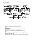
3-7. Gain and Offset
The previous adjustments as cutoff, drive, contrast or brightness act on the digital signal
(after the A/D converter) and assume a signal level of 0.7V p -p was supplied.
It is also possible to adjust the analogue signal (before the A/D converter) but these
adjustments should be kept to the default values in most cases of connecting one PC.
While DVI connection is used, this adjustment is not available.
ADJUSTMENT
In case if the display is connected to multiple output card or such equipment having several
individual outputs as video-wall processor, offset/gain adjustments will be the right an basic
adjustment to compensate each signal level difference from each outputs.
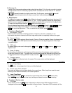
OFFSET then following by ADJ.R, ADJ.G and ADJ.B can be used for the low-signal-level
adjustment and GAIN , then ADJ.R , ADJ.G and ADJ.B for the high-level adjustment.
Adjustment hint: Cutoff and Drive adjustments can be done using internal test signal.