


37
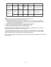
Apply 4 Apply custom setting 4 CS4
Apply 5 Apply custom setting 5 CS5
Apply 6 Apply custom setting 6 CS6
Apply 7 Apply custom setting 7 CS7
Apply 8 Apply custom setting 8 CS8
Apply 9 Apply custom setting 9 CS9
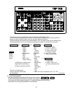
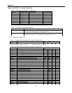
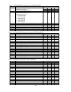
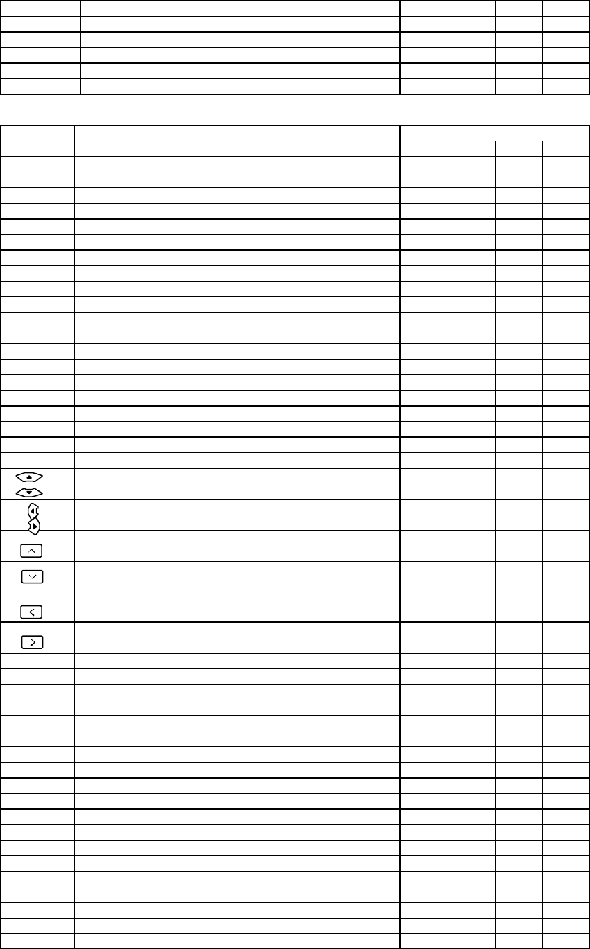
Table : 3 ADJUST MODE (Command to be used in ADJUST MODE)
Item Contents Key(CMD**)
CONT. Selects contrast adjustment ( ADC RGB gains ) CNT
BRIGHT Selects brightness adjustment ( ADC RGB offset) BRT
COLOR Selects color adjustment ( Video decoder ) COL
TINT Selects tint adjustment ( Video decoder ) TNT
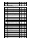
SHARP Selects picture sharpness adjustment ( video decoder)
SHP
CUTOFF Selects DLP low level adjustment (white balance Dark)
LOW
DRIVE Selects DLP contrast adjustment (white balance High) HIG
GAIN Selects gain adjustment ( RGB separate Gain ) GAN
OFFSET Selects offset adjustment ( RGB separate Offset ) OFS
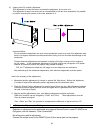
FLIP Switch image direction (1.2.3.4) FLP
POSI. Selects display position pixel base adjustment POS
CLOCK Selects sampling clock frequency adjustment CLK
PHASE Selects sampling clock phase adjustment PHS
CAP. Selects caption position adjustment mode CAP
MAG. Switches screen magnification (1x1 - 6x6 ) MAG
LAYOUT Selects screen layout selection mode LAY
TEST.P Selects internal test pattern TSP
ADJ.R Selects adjustment color Red SLR
ADJ.G Selects adjustment color Green SLG
ADJ.B Selects adjustment color Blue SLB
ADJ.RGB Selects adjustment color Red +Green + Blue SLA
Adjusts movement to up or data value increase VUP
Adjusts movement to down or data value decrease VDW
Adjusts movement to left VLF
Adjusts movement to right VRG
Change layer upward (uses in LAYOUT mode)
or test pa ttern number decrease (uses in TEST. mode)
DUP
Change layer downward (uses in LAYOUT mode)
or test pattern number increase (uses in TEST. mode)
DDW
Changes layout leftward (uses in LAYOUT selection
mode )
DLF
Changes layout rightwa
rd (uses in LAYOUT selection
mode )
DRG
CALL On screen display status or menu on or off DSP DOD DOF
WRITE Memorizing adjusted data VWR
SERVICE Entering SERVICE MODE SVC
SPECIAL Entering SPECIAL MODE SPC
ID.ALL Entering ID MODE IDA
ADJUST Exits ADJUST MODE (return to normal mode ) AJS AJN
MODE Enable INPUT SOURCE SWITCH in ADJUST mode MOD
AutoAdjust
Execute Auto-adjust at frequency converter AUT
SPEED Select Baud Rate SPD
0 Input 0 VN0
1 Input 1 or Flip 01 VN1
2 Input 2 or Flip 02 VN2
3 Input 3 or Flip 03 VN3
4 Input 4 or Flip 04 or Color mix Primary Red VN4
5 Input 5 or Color mix Primary Green VN5
6 Input 6 or Color mix Primary Blue VN6
7 Input 7 or Color mix on-off VN7
8 Input 8 VN8
9 Input 9 VN9