


21
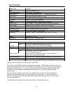
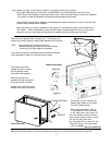
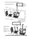
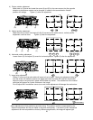
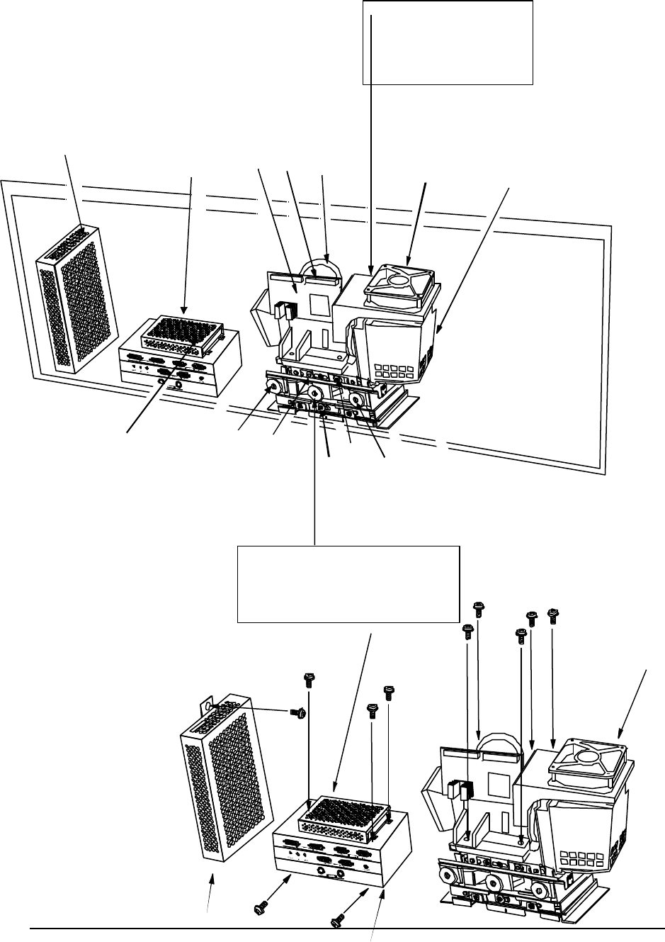
4. LOCATION OF KEY COMPONENTS AND FUNCTION MODULE
DISASSEMBLE
? ? ? ? ? ? ? ? ( ? ? ? ? ? ? )
(A).......... ? ? ? ? ? ?
(B).......... ? ? ? ? ? ? ? ? ? ? ? ?
(C).......... ? ? ? ? ? ? ?
(D).......... ? ? ? ? ? ? ?
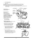
D L P? ? ? ?
(1)..... ? ? ? ? ?
(2)..... DM D? ? ? ?
(3)..... ? ? ? ? ? ? ?
(4)..... ? ? ? ? ? ?
(5)..... ? ? ? ? ?
? ? ? ? ? ? ?
? ? ? ? ? ? ? ? ?
? ? ? ? ? ? ? ? ? ? ?
(1)
(2)
(3)
(5)
(4)
(D)
(B)
(B)
(C)
(A)
Power
module
Lamp Ballast
DLP Light Engine
(1) Projection Lens
(2) DMD Control Board
(3) Lamp unit
(4) Input signal connector
(5) Exhaust Fan
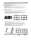
Control Module
Engine Mount,
Adjustment platform
(A)
Left
-
Right position adjustment
(B) Top to bottom Trapezoid, position
adjustment
(C) Right to left Trapezoid adjustment
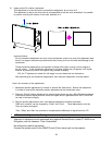
(D) Picture Size adjustment
This illustration indicates the key components
shown after rear panel has removed.
? ? ? ? ? ? ?
? ? ? ? ? ?
? ? ? ? ?
DLP? ? ? ?
? ? ? ? ? ? ? ? ?
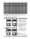
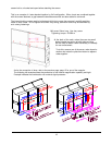
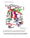
Right picture shows the
screws used to fasten each
blocks.
Removing the screws
written, every unit can be
removed.
This picture shows enlarged
screw size, actual screws are
much small.
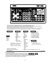
Lamp Ballast
Power Module
DLP Light Engine
Control Module
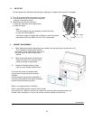
Lamp power
selection switch
is at here à