


29
Display flat field test signal and press “cutoff” or “drive”, then adjustment is possible.
In case of “offset” and “Gain” adjustments are placed at early signal process area and internal test
signal is generated later stage than this adjustment, thus flat field test signal needs to generate
from PC. Thus PC needs to have such signal generation software installed.
These color balance adjustments need to repeat several times from low signal level,
Then perform high signal level, again, returning back to low, then high level signal.
Repeat them several times to achieve better color balance.
This is the general idea of adjustments:
DVI input: only “Cutoff” and “Drive” by internal test signal or from PC
RGB1 or RGB2, one PC: “Cutoff” “Drive” by internal test signal or signal from PC and then, also
“Offset” “Gain” by signal from PC for sub-adjustment
RGB1 or RGB2 using video-wall processor: “Cutoff” “Drive” by internal test signal and “Offset”
“Gain” by the test signal comes from PC
In this case, Offset and Gain adjustments are much more important to
perform.
Video input: “Cutoff” “Drive” by internal test signal and possibly “Brightness” and
“Contrast” if needed by the signal from source
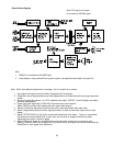
3-8. Clock frequency adjustment and phase adjustment
Supply fine pitch signal (such as Windows shut-down screen) and adjust CLOCK and PHASE
to eliminate moiré and jitter.
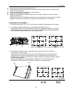
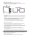
3-9. Image position adjustment
Initial image position should be adjusted using the mechanical adjustments with internal test picture
while electronic positions are at center so that all the unmagnified images appear at the same
position. Use POSI to electronically shift the image and CAP to select the position of the image for
magnification.
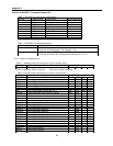
3-10. Screen Mode (frequency) Selection
Incoming signals are automatically synchronized and the relevant timing data is stored in memory so that
this data can be read out each time a particular source is recognized. RGB1 and RGB2 settings are
memorized separately. There are total of 10 signal memory areas available, additional frequencies differ
from VESA standard, they will be memorized for next time synchronization.
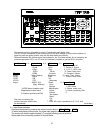
3-11. On-Screen-Display, OSD
The default condition is for the OSD to be on, this can be switched off by pressing the CALL button in
Adjust Mode.
ADJUSTMENT
It is possible to change the color of the OSD:
SPECIAL A = red, SPECIAL B = green, SPECIAL C = blue, SPECIAL 8 = white.
3-12. Video Enhancer
When video input is selected, the following adjustments are available: COLOR , TINT (NTSC only)
and SHARP
3-13. Picture in Picture
This is a feature which opens a small window and insert video image. The video signal input
Terminal adaptor need to place. The PC image is the base and small window has video signal