


33
The lamp used is UHP 100/120W, driven by the ballast, this lamp/ballast combination is made by
Philips enables to select lamp power for 100W or 120W by mechanical slide switch.
Do not replace the lamp with other model, a reflector which focuses the lamp beam is designed for
DLP use, with light tunnel application. Different lamp may not have right specification or lamp life
may be much different. The lamp for previous model, P500DL, is different from the P503DL lamp.
To avoid such confusion, the lamp connector has different shape so that other lamp will not fit.
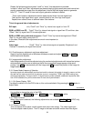
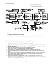
3. Power Supply PCB
The power supply consists of two sections, Power Factor Control and DC-DC conversion.
Incoming AC is rectified and supplied to the PFC converter, where the voltage and current phases are
matched, thus resulting power factor becomes 1.
The output of the PFC circuit is 380V DC and this is supplied to the main DC-DC converters and also
the Lamp Ballast.
The outputs of the main DC-DC converter are +12V, +6V and +4.5V.
Also, +12V which is connected to the fans and +5V for micro processor are separately prepared.
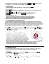
4. Lamp Ballast PCB
The Philips® 100/120W UHP lamp is driven by Philips ballast, power supply. The input voltage is
380V DC and high voltage trigger which is about 20kV pulse to ignite while lamp start period and
lamp supply voltage is given to continue to its discharge by about AC50V, plus non-flicker pulse drive
voltage is superimposed from lamp ballast output.
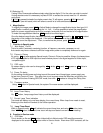
5. RS232C Control PCB
RS232C control signal or/and remote control from optional CT90000 are accepted, if both are
connected CT90000 has priority over RS232C communication line.
RS232C parallel cables need to use.
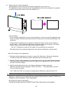
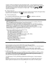
6. Video PCB (option)
Accepts PAL/NTSC/SECAM composite video signal and has a buffered output for loop-through.
Normally in case of PC picture, DVI internal link would be used for not so much active movement
pictures but in case of video picture, sometimes, DVI link may contain some picture frames of delay
occurred by each cubes so that images of all the cubes may not match but later the connection,
more movement delays may result.
In such occasion, Video output to next video input, video loop through may results better picture
by less delay composed.
Appendix-1
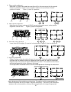
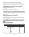
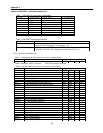
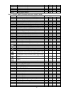
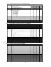
P503DL control board LED status
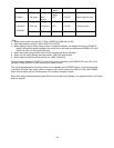
POWER FAN LAMP Blink time
OFF OFF OFF
ON (red) OFF OFF
ON (green)
ON (green) OFF Before Lamp lights
POWER OFF
STANBY
Preparation
POWER ON
ON (green)
ON (green) ON (green)
After Lamp lights up
ON (green)
ON (green) ON (green)
Normal
FAN STOP
ON (green)
Blink
(green)
OFF 0.2 SEC Lamp will shutdown
LAMP cannot
light
ON (green)
ON (green) OFF