


34
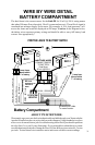
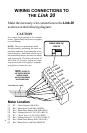
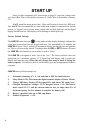
Make the necessary wire connections to the Link 20
as shown in the following diagram:
WIRING CONNECTIONS TO
THE
Link 20
1- BLACK
2- GREEN
3- ORANGE
4- BLUE
1
2
3
4
5
5- RED
6
8
7
8- BROWN
7- YELLOW
6- VIOLET
NOTE: BE SURE TO
USE TWISTED WIRE FOR
GREEN & ORANGE
AND YELLOW & BROWN
SHUNT SENSE PAIRS.
4 twisted pair cable
CAUTION
Use correct-sized screwdriver for terminal
screws. Tighten firmly but do not over-tighten
to avoid damage.
NOTE: The screw terminals are small.
During assembly and testing, the screw ter-
minals are tightened. To accommodate wires,
loosen the screws until flush with the top of
the terminal strip and pry open the wire clamp
with a paper clip. The holes will accept 16
AWG wire IF you have a clean cut, clean
strip and twist the wires tightly. Use needle-
nosed pliers to insert the wires.
[1] DC - Meter Negative (BLACK)
[2] Bat. 1 Shunt Sense Load Side (GREEN)
[3] Bat. 1 Shunt Sense Battery Side (ORANGE)
[4] Bat. 1 Voltage Sense (0.1–50 V DC) (BLUE)
[5] DC + Meter Power (9–40 V DC) (RED)
[7] Bat. 2 Voltage Sense (0.1–50 V DC) (VIOLET)
[6] Bat. 2 Shunt Sense Battery Side (YELLOW)
[8] Bat. 2 Shunt Sense Load Side (BROWN)
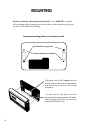
Meter Location
REAR VIEW OF
LINK 20