


171 ADAM-5560 Series User Manual
Chapter A RS-485 Networks
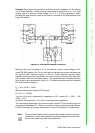
Example: Each input of the receivers has a nominal input impedance of 18 k feeding
into a diode transistor- resistor biasing network that is equivalent to an 18 k input
resistor tied to a common mode voltage of 2.4 V. It is this configuration, which
provides the large common range of the receiver required for RS-485 systems! (See
Figure D-5 below).
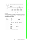
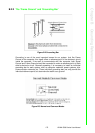
Figure A.5 Termination Resistor Locations
Because each input is biased to 2.4 V, the nominal common mode voltage of bal-
anced RS-485 systems, the 18 k on the input can be taken as being in series across
the input of each individual receiver. If thirty of these receivers are put closely
together at the end of the transmission line, they will tend to react as thirty 36k resis-
tors in parallel with the termination resistor. The overall effective resistance will need
to be close to the characteristics of the line. The effective parallel receiver resistance
RP will therefore be equal to:
R
P
= 36 x 10
3
/30 = 1200
While the termination receptor RT will equal:
R
T
= R
O
/ [1 - R
O
/R
P
]
Thus for a line with a characteristic impedance of 100 resistor R
T
= 100/[1 - 100/
1200] = 110
Since this value lies within 10% of the line characteristic impedance.
Thus as already stated above the line termination resistor RT will normally equal the
characteristic impedance Z
o
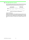
. The star connection causes a multitude of these discon-
tinuities since there are several transmission lines and is therefore not recommend.
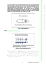
Note! The recommend method wiring method, that causes a minimum amount
of reflection, is daisy chaining where all receivers tapped from one trans-
mission line needs only to be terminated twice.