


ADAM-5560 Series User Manual 26
2.4 System Wiring and Connections
This section provides basic information on wiring the power supply, I/O modules and
communication port connection.
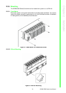
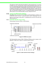
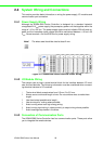
2.4.1 Power Supply Wiring
Although the ADAM-5560 Series Controller is designed for a standard industrial
unregulated 24 V
DC
power supply, they accept any power unit that supplies within the
range of +10 to +30 V
DC
. The power supply ripple must be limited to 200 mV peak-to-
peak, and the immediate ripple voltage should be maintained between +10 and +30
V
DC
. Screw terminals +Vs and GND are for power supply wiring.
Figure 2.11 ADAM-5560 Series Controller Power Wiring
2.4.2 I/O Module Wiring
The system uses a plug-in screw terminal block for the interface between I/O mod-
ules and field devices. The following information must be considered when connect-
ing electrical devices to I/O modules.
1. The terminal block accepts wires from 0.5 mm 2 to 2.5 mm.
2. Always use a continuous length of wire. Do not combine wires to make them
longer.
3. Use the shortest possible wire length.\
4. Use wire trays for routing where possible.
5. Avoid running wires near high energy wiring.
6. Avoid running input wiring in close proximity to output wiring where possible.
7. Avoid creating sharp bends in the wires.
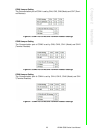
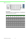
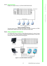
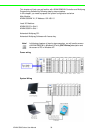
2.4.3 Connection of Communication Ports
The ADAM-5560 Series Controller has four communication ports. These ports allow
you to integrate the remote devices.
Note! The wires used should be sized at least 2 mm.