


Using the STK594 Top Module
2-4 FPSLIC STK594 User Guide
2819A–FPSLI–07/02
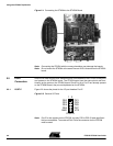
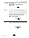
2.5 TOSC Switch The AT94K device provides dedicated I/O pins for TOSC1 and TOSC2, rather than
sharing with the general purpose I/O pins. The TOSC switch selects whether or not the
32 kHz crystal is connected to the pins of the device.
Figure 2-5 shows a simplified block schematic on how this is implemented.
Figure 2-5.
TOSC Block Schematic
2.6 Universal
Asynchronous
Receiver
Transmitter
(UART)
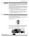
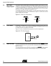
Unlike traditional AVR microcontrollers, the AT94K device provides the option of having
separate I/O pins for the UARTs rather than sharing with the general purpose I/O pins.
Figure 2-6 shows the pinout of a header for the dedicated UART pins.
Figure 2-6.
UART Header
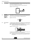
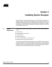
2.6.1 Second RS-232C
Port
The AT94K device has an additional UART. The RS-232 port on the STK594 board has
in addition to the RXD and TXD lines support for RTS and CTS flow control. Figure 2-7
shows a simplified block schematic on how this is implemented.
Note:
The UART in AT94K devices does not support hardware RTS or CTS control. If
such functionality is needed, it must be implemented in software.
Figure 2-7.
UART Block Schematic
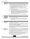
This UART can also be used from devices placed in the STK500 board. Simply connect
the appropriate port pins to RXD and TXD on the STK594 board.
Note:
If no software RTS/CTS flow control is implemented, a jumper shorting RTS and
CTS will ensure correct communication with an external application that uses
such flow control.
TOSC1
TOSC2
32 kHz
TOSC
Switch
FPSLIC
TX0
TX1
RX0
RX1
1 2
UART
RxD TxD
CTS RTS
RS-232/Logic Level
Converter
8
7
3
2
4
6
5
RS232 SPARE2