


FPSLIC STK594 User Guide 2-1
Rev. 2819A–FPSLI–07/02
Section 2
Using the STK594 Top Module
2.1 Preparing the
STK500 for Use
with the STK594
Prior to using the STK594 with the STK500, it is necessary to make a few adjustments
to the STK500 Starter Kit to allow for proper operation of Atmel’s AT94K FPSLIC
devices.
2.1.1 Adjusting VTARGET
for the AT94K
Devices
According to the AT94K Series datasheet, the V
CC
operating voltage is specified where
{V
CC
|3.0<V
CC
= 3.6} Volts, with respect to ground. The STK594 board requires that
theSTK500boardsuppliesaV
CC
within the operating range for the AT94K devices.
Prior to using the STK594 board, it is necessary to adjust the VTARGET to a value
between 3.0 and 3.6V. For more information on adjusting VTARGET from within AVR
Studio, consult section 5.3.5.1 of the STK500 User Guide, available on the Atmel web
site (www.atmel.com).
Note:
It may be necessary to adjust the V
DD
voltage, see “Split Power Supply Support”
on page 6 of this section for more information.
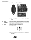
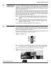
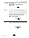
2.1.2 Connecting the
STK594 to the
STK500 Starter Kit
The STK594 should be connected to the STK500 expansion header 0 and 1. It is impor-
tant that the top module is connected in the correct orientation as shown in Figure 2-1
on page 2. The EXPAND0 written on the STK594 top module should match the
EXPAND0 written beside the expansion header on the STK500 board.