


-21-
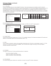
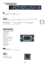
11.0 Connector Specifications
DC
CONTROL
RGB/YPbPr and Display
2.1mm Power Connector (12 volts)
Center is Positive Outer Shell is Ground
Pins 1,3,5 Note: Pin 2 must be disabled with jumper J9 removed (factory default)
Pin 1 - Ground Pin3-TX Pin5-RX
Pins 1,2,4,6
Pins 1,2: PiP Swap Pins 1,4: Channel + Pins 1,6: Channel -
Pins 1,4,6: PiP On/Off Pins 1,2,4,6: PiP Move
RS232 -
Contact Closure -
15 Pin VESA VGA Connector
Note: Pin 2 must be enable with jumper J9 on XTune
1 Red video / Pr
2 Green video / Y
3 Blue video /Pb
4 Not used
5 Ground
6 Red (Pr) return (ground)
7 Green (Y) return (ground)
8 Blue (Pb) return (ground)
9 Key (no pin)
10 Sync return (ground)
11 Not used
12 Not used
13 Horizontal sync
14 Vertical sync
15 Not used
Tip - Right Ring - Left Sleeve - Ground
1 Y Ground
2 C Ground
3 Y Intensity (Luminance)
4 C Color (Chrominance)
Audio
S-Video
TRS Connector 1/8”
4 pin Mini Din