Bosch Security Systems
Divar | Installation Manual | Hardware setup EN | 4-7
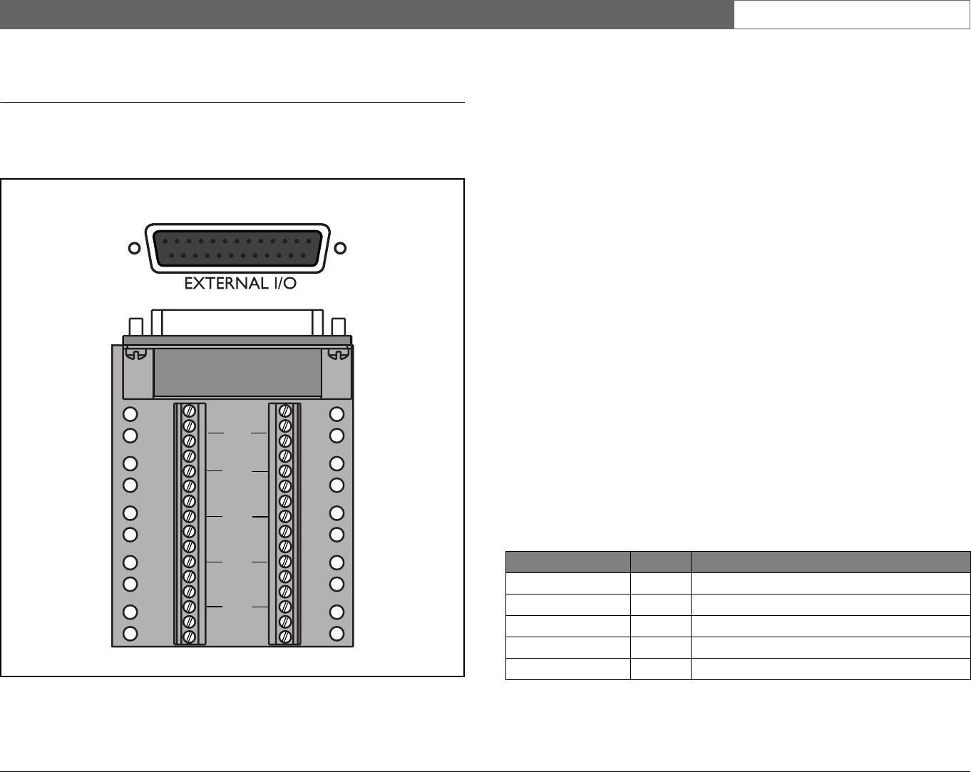
External I/O connection
Alarm inputs and outputs are supplied via a 25-pole D-type socket. The screw
terminal input/output connection board supplied with the unit simplifies all
alarm connections to the unit.
Connecting the Inputs
Each (alarm) input line can be switched by a relay contact from devices such as
pressure pads, passive infra-red detectors, smoke detectors and similar devices.
Wire them as either N/O or N/C. You can configure the alarm inputs as N/O or
N/C in the menu system. The default is N/O.
Connecting the Alarm Outputs
The four alarm output relays respond to input alarms and triggers. You can
configure the alarm outputs as N/O or N/C in the menu system. The relays are
active for the duration of the driving event. Connect the application to the alarm
output relays (resistive loads only). Do not exceed 30 Vac, 40Vdc, 500 mA
(continuous) or 10VA on an alarm output relay's contacts. The contacts must not
be used at AC line voltages.
Specifications
Alarm input impedence: Internal pull-up 10K to +5V
Input voltage range: -0.3V min to 30V max
Input voltage treshold: Low voltage 0.8V max
High voltage 2.4V min
Switching current (resistive): 500mA max
Carrying power: 10VA max
Switching voltage (resistive): 30 Vac / 40 Vdc max
External I/O - 25-pole D-type socket
1A
1B
2A
2B
R
E
L
A
Y
3A
3B
4A
4B
GND
1
2
GND
9
10
3
4
GND
11
12
5
6
GND
13
14
7
8
15
16
IN
IN
IN
IN
13
1
14
25
Panel view
Signal name: Pin no. Description
Alarm_in_1 1 Alarm input 1
Alarm_in_2 2 Alarm input 2
Alarm_in_3 3 Alarm input 3
Alarm_in_4 4 Alarm input 4
Alarm_in_5 5 Alarm input 5


