


10
© 2006 directed electronics.
check for any additional screws you may have missed.
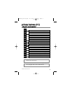
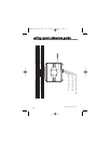
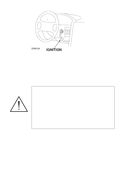
Once the lower dash panel has been removed, locate the ignition
harness at the back of the key cylinder. This is usually a group of
thicker wires. With the ignition harness exposed, use your LED
tester to find your power and ignition wires.
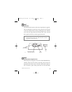
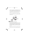
Place the black lead of the LED tester to a clean metal surface in
the kick panel area and secure it. Probe one of the thicker gauge
wires. The color and identity of your specific vehicle wiring can
be obtained at www.readyremote.com. With the key in the OFF
position, test the suspect wire. The constant power wire will illu-
minate the Red LED on the test probe.
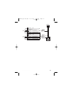
Once the constant power wire has been identified, solder the
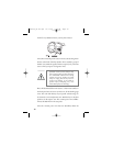
warning! On vehicles with air bags or sup-
plemental restraint systems (SRS) you may
notice a bright yellow tube with small wires
in it marked SRS underneath the steering
column near the key cylinder. DO NOT
tamper or unplug these for any reason to
prevent costly damages to your vehicle or
personal injury. Tampering may cause
unintended deployment of airbags.
G21994_04-06.qxd 12/11/06 3:36 PM Page 10