


21
© 2006 directed electronics
■
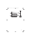
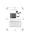
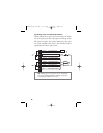
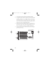
HH11//44 BBRROOWWNN//BBLLAACCKK::
Connect the brown/black wire
to the master switch side of the unlock wire. The master
switch side will show (+)12V when the master switch is in the
unlock position and (-) ground when the master switch is in
the middle position.
■
HH11//33 BBLLUUEE//BBLLAACCKK::
Connect the blue/black wire to the
other side of the unlock wire.
■
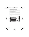
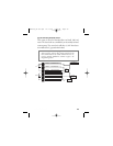
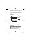
HH11//22 VVIIOOLLEETT::
This wire must be connected to a constant
(+)12 volts. The best connection point for this wire is the con-
stant (+)12V supply for the door lock switch*, or directly to the
positive (+) battery post with a fuse at the battery post. (See both
notes above.)
*note: Except in GM cars with retained accessory power
(RAP). In these vehicles, the (+)12V feed to the door lock
switches is turned off if the doors are closed for any length
of time.
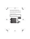
note: Most direct-wired power lock systems require 20-30
amps of current to operate. Connecting the violet/black
wire to a poor source of voltage will keep the door locks
from operating properly.
G21994_04-06.qxd 12/11/06 3:36 PM Page 21