


26
© 2006 directed electronics.
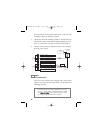
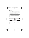
1. Cut the output wire from the door lock switch/key cylinder.
2. Test with the meter from the switch side of the cut door lock
switch/key cylinder wire to a reliable constant (+)12V source.
Some good constant (+)12V references are the power input
source to the door lock switch/key cylinder, the ignition switch
power wire, or the (+) terminal of the battery.
3. Operate the door lock switch/key cylinder in both directions to
determine the resistor values. If the multimeter displays zero resis-
tance in one direction, no resistor is needed for that direction.
4. Once the resistor value(s) is determined, refer to the wiring dia-
gram for proper wiring.
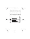
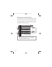
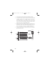
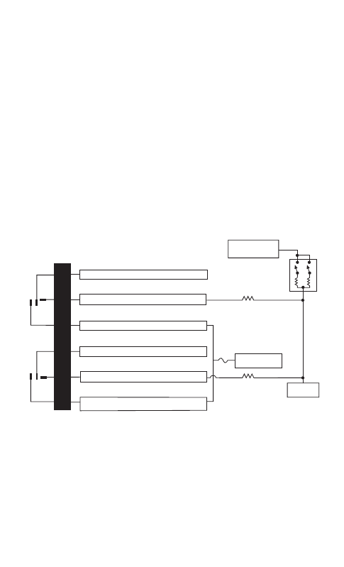
H2/7
H2/6
H2/5
H2/4
H2/3
H2/2
LOCK
RELAY
UNLOCK
RELAY
#87
#87A
#30
#87
#87A
#30
BCM
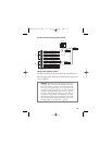
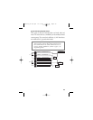
GREEN/BLACK LOCK #30 COMMON (OUTPUT)
WHITE/BLACK NOT USED
VIOLET/BLACK LOCK #87A NORMALLY OPEN (INPUT)
BROWN/BLACK NOT USED
BLUE/BLACK UNLOCK #30 COMMON (OUTPUT)
VIOLET UNLOCK #87 NORMALLY OPEN (INPUT)
VIOLET & VIOLET/BLACK ARE COMMON AT FUSE HOLDER
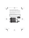
15A
VEHICLE FUSED
+12 VOLT CONSTANT
LOCK RESISTOR
(IF REQUIRED)
UNLOCK RESISTOR
(IF REQUIRED)
DOOR LOCK SWITCH/
KEY CYLINDER
UNLOCK
(+)12V
CONSTANT FUSED
LOCK
G21994_04-06.qxd 12/11/06 3:36 PM Page 26