


20
© 2006 directed electronics.
It is critical to identify the proper wires and locate the master
switch to interface properly. Locate wires that show voltage when
the switch is moved to the lock or unlock position. Cut one of
the suspect wires and check operation of the locks from both
switches. If one switch loses all operation in both directions then
you have cut one of the correct wires and the switch that is
entirely dead is the master switch. If both switches still operate
in any way and one or more door motors have stopped
responding entirely, you have cut a motor lead. Reconnect it and
continue to test for another wire. Once both wires have been
located and the master switch identified, cut both wires and
interface as described in the following paragraphs.
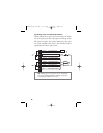
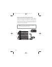
■
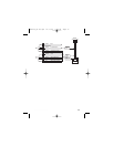
HH11//77 WWHHIITTEE//BBLLAACCKK::
Once both door lock wires are
located and cut, connect the white/black wire to the master
switch side of the lock wire. The master switch side will show
(+)12V when the master switch is operated to the lock position
and (-) ground when the master switch is in the middle position.
■
HH11//66 GGRREEEENN//BBLLAACCKK::
Connect the green/black wire to
the other side of the lock wire. This is the motor side of the lock
wire and it goes to the lock motor through the slave switch.
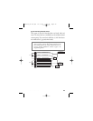
■
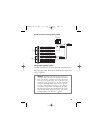
HH11//55 VVIIOOLLEETT//BBLLAACCKK::
This wire must be connected to
a constant (+)12 volts. The best connection point for this wire is
the constant (+)12V supply for the door lock switch*, or direct-
ly to the positive (+) battery post with a fuse at the battery post.
caution: If these wires are not connected properly, you
will send (+)12V directly to (-) ground, possibly damag-
ing the alarm or the factory switch.
G21994_04-06.qxd 12/11/06 3:36 PM Page 20