17
SETUP AND CONNECTIONS
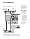
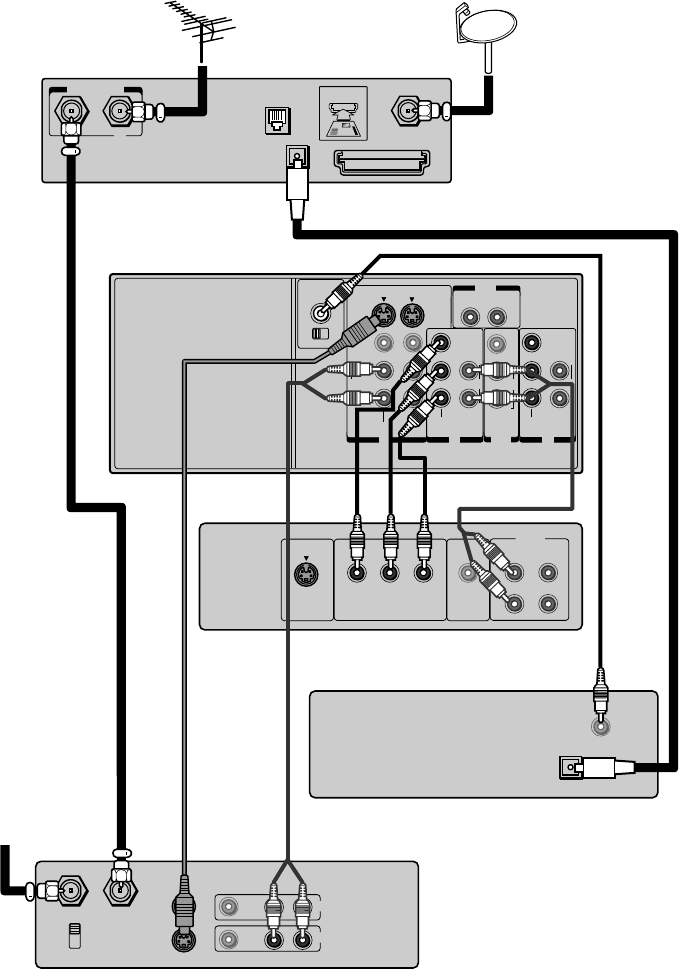
THE ADVANCED CONNECTION
TV, VCR, and DVD Player and Audio Amp.
ANTENNA
-IN
A B
SATELLITE
-IN
ACCESS CARD
PHONE
JACK
DIGITAL
AUDIO-IN
TOP OF CARD
FACE DOWN
OUT
IN IN
HD 1 HD 2
IN
CHANNEL IN
ON OFF
OUT
R
L
VAR
AUDIO
VIDEO
L/
MONO
AUDIO CENTER
L
R
P
B
P
R
Y
L/
MONO
AUDIO
AUDIO AUDIO
S-VIDEO
VIDEO
R
VIDEO-1 VIDEO-2
COLOR
STREAM
R
L
R
P
B
P
R
Y
AUDIO
COLOR
STREAM
ANT
(
75
)
ANT-1 OUT ANT- 2
IN from ANT OUT to TV
CH 3
CH 4
VIDEO AUDIO
LR
IN
OUT
Satelite IN
VIDEO
OUT
S-VIDEO
AUDIO
COMPONENT VIDEO
OUT
L
R
L
R
Cr
CbY
S-VIDEO
TO
CENTER
SPEAKER
DIGITAL
OPTICAL
AUDIO-OUT
Please Read Before Using the Digital Audio Out Jack
This TV’s optical digital output jack fully complies with the international standard governing this type
of jack (IEC958), and is designed for connection to a Dolby Digital (AC-3 or PCM) receiver or
Dolby Digital (AC-3 or PCM) decoder. Older equipment, some of which is not fully compliant with
IEC958, may not be compatible with the Dolby Digital bitstream. Such a connection using anything
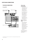
After you have made your
connections, program the TV to tune
to the correct video input channel to
see and hear audio and video from
the attached component (VCR,
DVD player, etc.). Program your TV
as described in the “System Options
and Preferences” section of this
Manual.
How to view your
DVD and VCR:
•To watch the VCR in this
connection, press TV/
VIDEO on the remote
control until the correct
video input appears (in this
example, V-1). Note that
because the digital decoder
is in the TV, not the VCR,
you cannot record digital
channels with this hook-up.
•To watch the DVD player
in this connection, press
TV/VIDEO on the remote
control until the correct
video input appears (in this
example, CS-1).
Some cable systems may require a
“conversion box.” If so, consult your
cable company’s box tuning
instructions for details.
Cable or any alternate
RF signal, such as a
digital or analog off-air
antenna
Satellite dish
antenna
TV
Stereo VCR
Cable or
off-air antenna
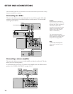
Audio amplifier with optical INPUT
TV
DVD


