


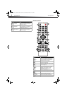
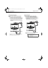
TV components
5
DX-24L200A12
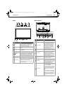
Front Back and Side
# Item Description
INPUT
Press to open the INPUT SOURCE list, then
press
or to select a video input source.
For more information, see “Selecting the
video input source” on page 18.
MENU
Press to open the on-screen menu. For more
information, see “Navigating the menus” on
page 18.
CH
/CH
Press to go to the next or previous channel in
the channel list.
VOL+/VOL– Press to increase or decrease the volume.
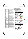
(Power)
Press to turn your TV on or off (standby
mode). When your TV is in standby mode,
power still flows through it. To completely
disconnect power, unplug the power cord.
Remote sensor
Receives the signals from the remote control.
Do not block.
Power indicator
Lights blue when your TV is turned on.
Lights red when your TV is in standby mode.
Flashes red when your TV receives no signal
from VGA and enters DPMS mode.
For more information, see “Turning your TV
on or off” on page 18.
POWERINPUT
+LOV-LOVUNEM
1
6 7
2 3 4 5
1
2
3
4
5
6
7
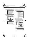
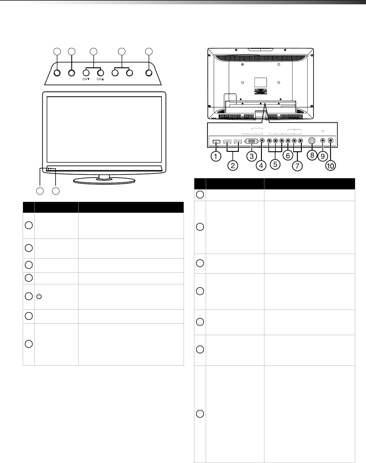
# Item Description
Service Port For software update only. Do not use.
HDMI1/HDMI2
Connect an HDMI device to these
jacks. An HDMI cable carries both
video and sound. You do not need to
make an audio connection for an
HDMI device. For more information,
see “Connecting a DVD or Blu-ray
player” on page 11, or “Using DVI
(same as HDMI but requires a sound
connection)” on page 12.
PC IN VGA
Connect the video for a computer to
this jack. For more information, see
“Connecting a computer” on page 14.
PC IN AUDIO
Connect the audio from a computer or
a DVI device to this jack. For more
information, see “Connecting a
computer” on page 14 or “Using DVI
(same as HDMI but requires a sound
connection)” on page 12.
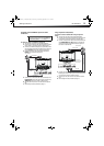
COMPONENT IN Y, P
B, PR
Connect the video for a component
video device to these jacks. For more
information, see “Using component
video (better)” on page 9.
AV IN VIDEO
Connect the video for a composite
video device, such as a VCR, to these
jacks. For more information, see “Using
composite video (good)” on page 10,
or “see "Using VGA" on page 14.
L/R AUDIO IN
The component video jacks
(COMPONENT IN Y, P
B, PR) share
these audio jacks with the composite
video jack (AV IN VIDEO).
Connect the audio for a component
video device connected to the Y, P
B,
PR jacks. For more information, see
“Using component video (better)” on
page 9.
-OR-
Connect the audio for a composite
video device connected to the AV IN
VIDEO jack. For more information, see
“Using composite video (good)” on
page 13 or see "Connecting a VCR" on
page 13.
YP
B
P
R
L -
AUDIO
-
R
COMPONENT IN
ANT / CABLE
AV IN
VIDEO
HDMI 2 HDMI 1 / DVI VGA
PC / DVI
AUDIO IN
DIGITAL
OUTPUT
SERVICE
PORT
1
2
3
4
5
6
7
DX-24L200A12_11-0584_MAN_ENG_V1.book Page 5 Wednesday, September 14, 2011 12:59 PM