


4
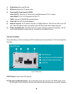
1) SD Card Slot: Slot to insert SD card.
2) IR Receiver: Receiver for IR remote control.
3) Alarm Input(2), Alarm Output(1) & RS232:
Alarm Input (2) - Connect up to 2 alarm inputs, selectable between N.O./N.C. contacts.
Alarm Output (1) - N.C or N.O type alarm out (form “C”).
RS232 - Connect to RS232/RS485 compatible device.
4) Power LED: This LED ON indicates Power on.
5) Network Connector: RJ-45 network connection 10/100Mbps Ethernet. There are two LEDs on the LAN
jack; Green LED means network is connected, amber LED flickers when data is being exchanged.
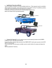
6) Philips mounted/Pin-torx: Use Philips screw for an easier mounting to prevent over-tightening. Use Pin-
torx for a safe installation to prevent cam-out. A screwdriver is included for Pin-torx.
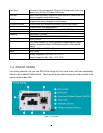
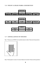
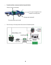
REAR PANEL
During initial setup you will be connecting your DVR to multiple input and output devices. This is done through the
rear panel.
Figure 1-2 Rear Panel
○
○○
○
1
GPS Antenna: Connect to the GPS antenna.
○
○○
○
2
Power Input and Switched Ignition: 1 pin is reserved for power input; connect to 10V~36VDC power source.
1 pin is for ignition control; connect to the other vehicle devices to avoid excess power consumption at ignition.