


10
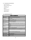
1.8 VIDEO INPUTS/OUTPUTS INSTALLATION
Cameras and CCTV monitors must use copper center conductor/copper braid 75 Ohm video cable (e.g. RG-59,
RG-6, RG-11) with BNC connectors.
To avoid impedance mismatch and undesired loss/reflections, 50 Ohm coax cable (e.g. RG-58), or 75 ohm foil
shield antenna cable and other types of coaxial cable are not compatible.
All connected video sources must provide a 1 Vpp NTSC or PAL standard video signal.
When converting other transmission types (twisted pair, fiber optics, radio) for the video inputs, be sure to verify
accurate receiver calibration and signal levels.
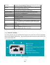
ATTENTION: In order for the system to auto-detect the appropriate video format (NTSC or PAL), make sure that
there is a video signal on video input 1 upon power-up.
1.9 AUDIO INSTALLATION
This DVR provides 2 line level audio inputs and 1 line level audio output.
ATTENTION: The direct connection of a non-amplified microphone is not supported (a microphone amplifier is
required). The audio output requires an amplifier to drive a speaker or headphones.
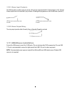
The installation must be connected with audio coax cable and RCA plugs.
AUDIO RECORDING FUNCTIONALITY:
Audio recording is activated / deactivated in the Camera Menu for Camera #1~2 respectively. Please check and
always comply with local laws and regulations when using audio recording.
The audio channel is always recorded together with video and is independent of the image recording rate. Though
the audio record control is done in the Camera #1~2 screen, there is no specific camera allocation.
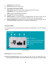
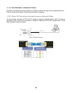
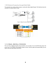
1.10 ALARM CONTACTS INSTALLATION
The alarm inputs can be used to start recording or for recording rate adjustment. In addition, alarm reactions such
as camera display on the monitor, buzzer, e-mail and network alarm are available. The alarm output relay can be
switched if required. Alarm input response actions can be controlled according to a flexible schedule.