


VN-Matrix 300 • Introduction 4
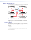
VN-Matrix 300 System Overview
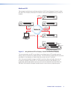
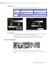
In this example either of the two encoder streams may be routed to any of the three decoder
units. The VN-Matrix 300 labelled IP Rx is the controller for the system.
Network
VN-MATRIX 300 SERIES
SERIAL DIGITAL VIDEO OVER IP
LAN-1
LAN-2
STATUS
ALARM
TEST
VN-MATRIX 300 SERIES
SERIAL DIGITAL VIDEO OVER IP
LAN-1
LAN-2
STATUS
ALARM
TEST
VN-MATRIX 300 SERIES
SERIAL DIGITAL VIDEO OVER IP
LAN-1
LAN-2
STATUS
ALARM
TEST
VN-MATRIX 300 SERIES
SERIAL DIGITAL VIDEO OVER IP
LAN-1
LAN-2
STATUS
ALARM
TEST
VN-MATRIX 300 SERIES
SERIAL DIGITAL VIDEO OVER IP
LAN-1
LAN-2
STATUS
ALARM
TEST
Monitoring &
Control
IP Tx 1
IP TX 2
IP Rx (a)
IP Rx (b)
IP Rx (c)
Decoder Configured as Controller
System Control
Figure 1. VN-Matrix 300 In Use to Transmit (Encode) and Receive (Decode)
Configuration of each device, including which source is displayed on which display, can
be achieved by any PC on the same network, using the VN-Matrix 300 Integrated Web
Management System
Data Transport Methods
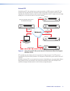
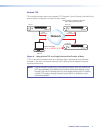
Source (video) data from a VN-Matrix 300 Encoder can be distributed to multiple displays/
decoders (one-to-many) or to a single display/decoder (point-to-point).
Video data is transported from the source (encoder) to the display (decoder) using one of
three methods:
z Multicast RTP
z Unicast RTP
z Unicast TCP
A description of each method, together with its advantages and disadvantages, can be
found on the following pages.