


13
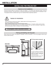
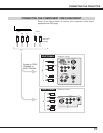
CONNECTING THE PROJECTOR
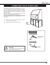
CAUTION
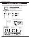
When connecting the peripheral equipment to the projector, please observe the following precautions:
l Be sure that the each equipment is turned off.
l Connect the cable securely to the respective terminal.
l When removing the cable, never pull the cord. Hold the plug of the cable and remove it.
l When operating the peripheral equipment, turn off the other equipment that is not used.
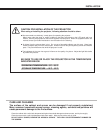
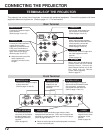
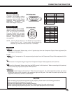
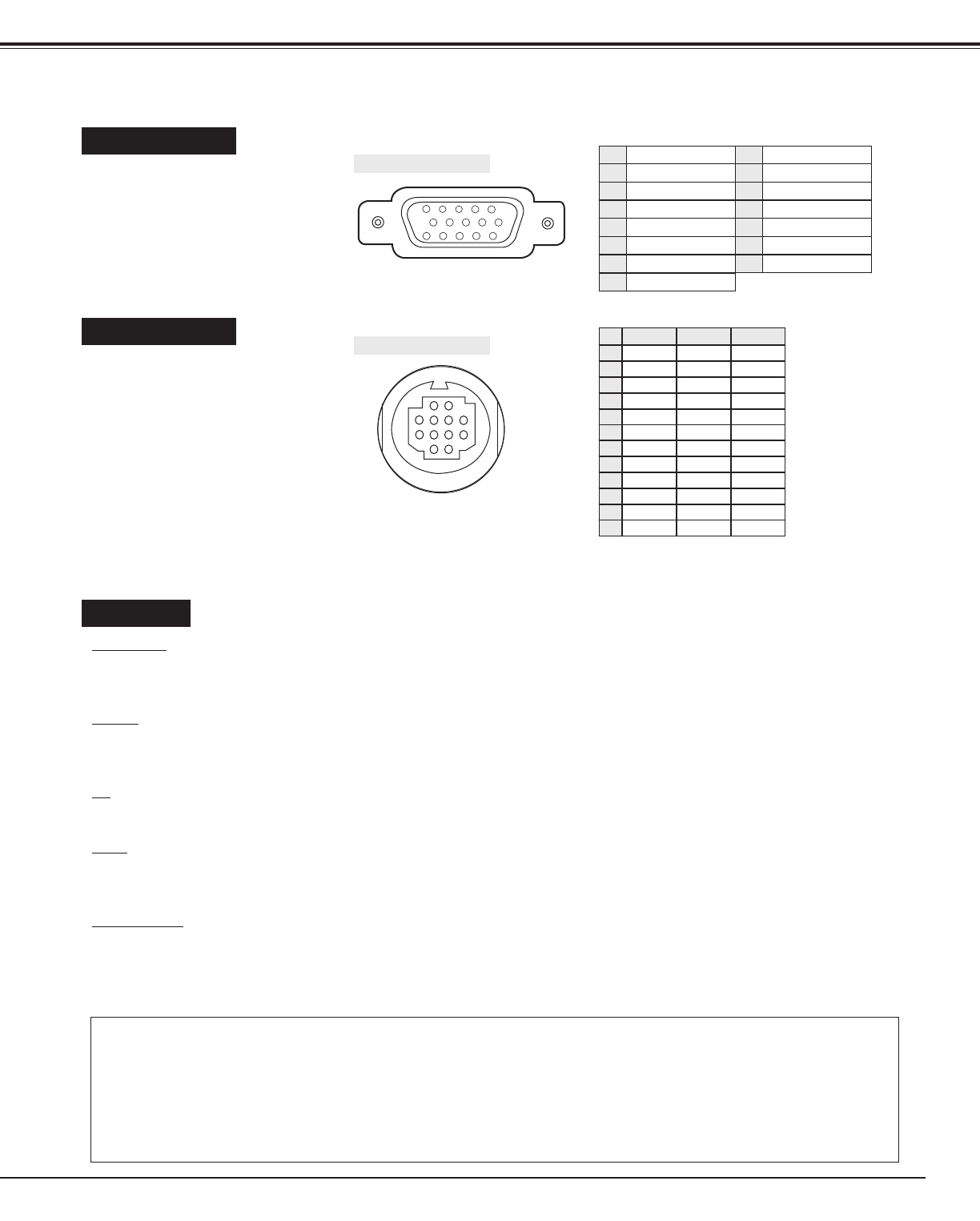
COMPUTER IN
Terminal : HDB15-PIN
Connect the display output
terminal of the computer to the
projector with the VGA Cable
(supplied). When connecting the
Macintosh computer the
MAC/VGA Adapter is required.
CONTROL PORT
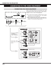
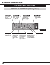
VIDEO IN
VIDEO / Y
Connect the Composite Video output, or the Y signal output from the Component Output Video equipment (like
DVD player) to this terminal.
C / Cb
Connect the C component or Cb component signal output from the Component Output Video equipment to this
terminal.
Cr
Connect the Cr component signal output from Component Output Video equipment to this terminal.
BNC
Connect the Composite Video output from the BNC terminal to this terminal. When connecting to this terminal,
do not connect any input source to the VIDEO terminal.
AUDIO R / L
Connect the Audio output to this terminal. When the audio output of the audio equipment is stereo, be sure to
connect the right and left channels to the respective right and left jacks. And when the audio input of the audio
equipment is monaural, connect it to the left jack.
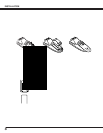
Terminal : MULTI-POLE 12-PIN
When controlling the computer
with the projector's Wireless
Remote Control Unit, connect
control port (PS/2, Serial or ADB
port) on your computer to this
terminal. (Three types of cables
are supplied.)
5 12
34
10
9 678
15 14 13 1112
12
3
4
5
6
7
8
9
10
1112
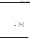
Red Input
Ground (Horiz.sync.)
Green Input
Sense 2
Blue Input
Ground (Red)
Ground (Green)
Ground (Blue)
1
5
2
4
3
6
7
8
Non Connect
Horiz. sync.
Ground (Vert.sync.)
Sense 1
Sense 0
Vert. sync.
Reserved
9
13
10
12
11
14
15
-----
CLK
DATA
-----
-----
-----
-----
-----
GND
-----
-----
-----
T X D
-----
-----
-----
R X D
-----
READY
-----
GND
-----
-----
-----
-----
ADB
-----
-----
-----
-----
-----
-----
GND
-----
-----
-----
PS/2 Serial ADB
1
2
3
4
5
6
7
8
9
10
11
12
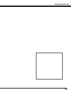
Pin Configuration
Pin Configuration
NOTE : The R X D port (5th pin on the Serial Port is provided on
Control Port 1 only. If your control the projector by
computer you must connect Control Port 1 connector.