7
ENGLISH
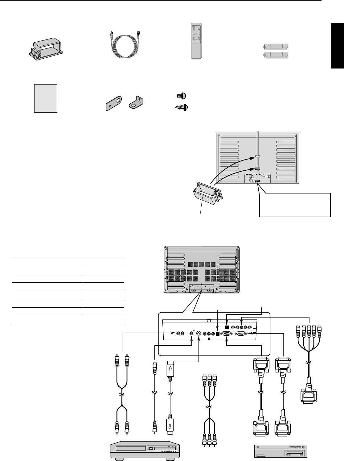
Connectors
AUDIO INPUT Pin jack
VIDEO INPUT BNC
S-VIDEO INPUT S terminal
COMPONENT VIDEO INPUT
BNC
RGB 1 INPUT 15-pin mD-sub
RGB 2 INPUT BNC
RS-232C 9-pin D-sub
Checking Accessories
Cable clamper × 2 Power cord Remote controller × 1 AA battery × 2
User’s Manual × 1 Bracket × 2 (2 types) Screw × 2 (2 types)
Cable clampers
• The accessory cable clampers are for fastening the connected
signal cables and a power cable. When installing this display
on a wall or ceiling, insert the cable clampers into the holes on
the rear of the display.
∗ When connecting separately pur-
chased BNC terminals, conversion
connectors are required between the
pin jacks and the BNC terminals, so
purchase these also.
∗ Cables connecting the personal com-
puter vary according to the type of
machine, so consult your product
dealer.
ACCESSORIES
Connecting to External Equipment
Cables for connecting external equipment must be
purchased separately.
AB
USER’S
MANUAL
Cable clamper
(Attach as in the illustration.)
Bundle connecting cables so
that they lead downwards, as
in the illustration.
Screw A (10 mm)
Screw B (20 mm)
RS-232C
RGB 1 INPUT
RGB 2 INPUT
VIDEO INPUT
COMPONENT
VIDEO INPUT
(color difference
input)
AUDIO INPUT
RGB 1
SYNC SW
TTL/ANALOG (75Ω)
RGB 2
SYNC SW
TTL/ANALOG (75Ω)
S-VIDEO
INPUT
To component
video output
terminal
Connecting to AV equipment
Connecting to PC
To RS-232C
terminal
Display
(to analog
RGB
output
terminal)
Display
(to analog RGB
output terminal)
To S-video
output
terminal
To video
output
terminal
To audio
output
terminal
PDS4207W-H × 3
PDS4207E-H × 1


