


0150-0193G 10 DVMRe Triplex
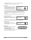
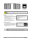
14. RS485 Port 2 Connector: For connecting to keyboard and other RS485 devices.
15. RS232 Port 2: For Event Generation and ASCII Text insertion.
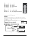
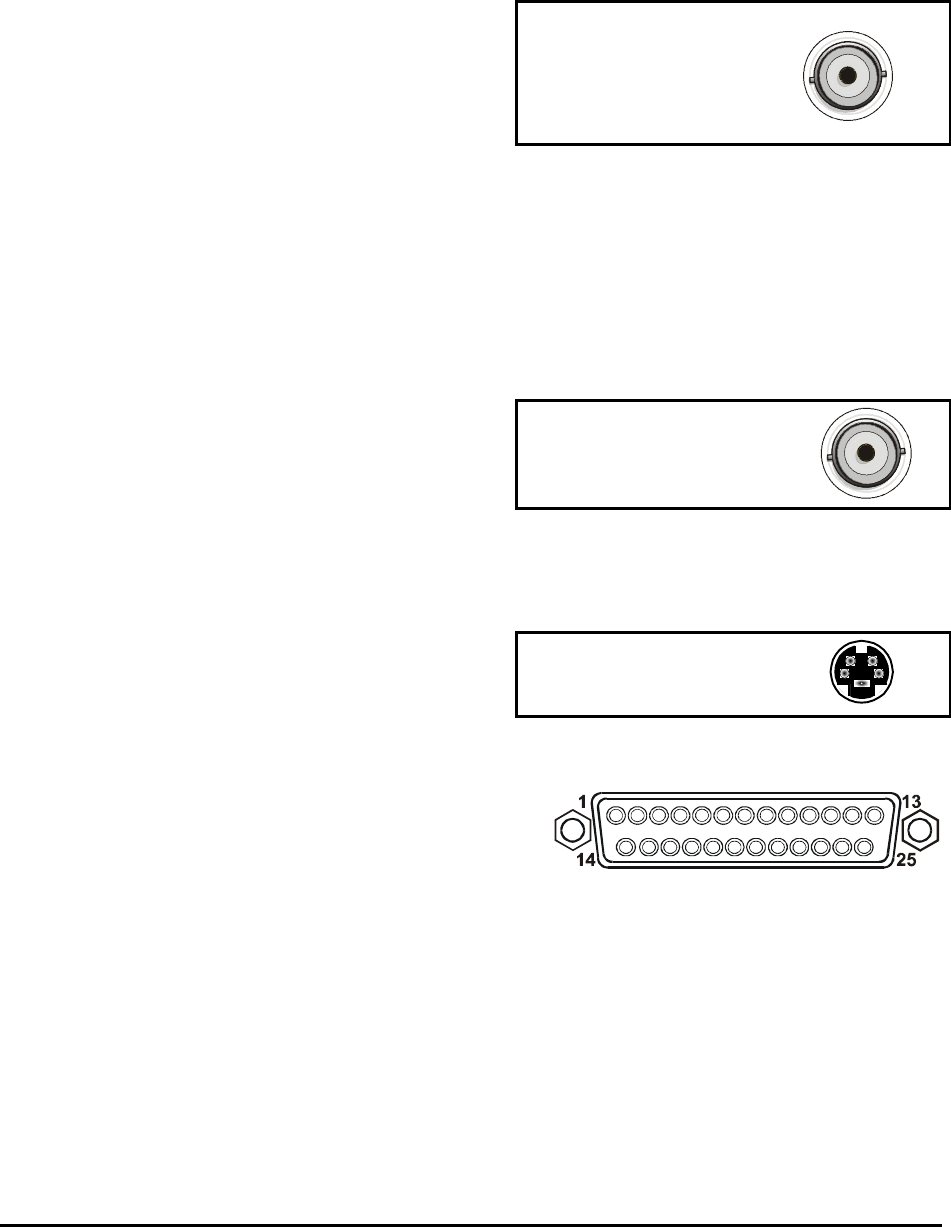
Camera Inputs
Cable: 75-Ohm Coaxial
Connectors: BNC
Auto Terminating: Yes
Passive Looping: Yes
There are two BNC jacks for each camera. Either
jack can receive a camera signal. The signal is
looped (directly connected to the other jack), making
the camera signal available to other equipment.
The camera input connectors are Auto Terminating.
This means that the input signal will automatically be terminated with 75-Ohms unless a 2
nd
cable is
connected to the 2
nd
BNC connector of the same camera input. Make sure there is 75-Ohm
termination at the end of the video line if the signal is looped through the DVMRe
Triplex.
Time base correction is performed during digital capture. As a result, cameras do not require
synchronization.
See section 3.14 for information about disabling unused camera jacks in the menu system.
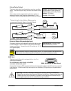
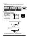
Composite Monitor Output
When connecting directly from the DVMRe Triplex to
the monitor, select the 75-Ohm impedance setting on
the monitor.
Cable: 75-Ohm Coaxial
Connectors: BNC
If an additional device is connected to the monitor’s looping output, set the termination of the additional
device as 75-Ohm, and set the termination of the monitor as Hi-Z (High Impedance).
Y/C Monitor Output
Y/C video output has a 4-pin mini-DIN style
connector. This style of connection is also referred to
as SVHS and S-Video.
Cable: 75-Ohm Coaxial
Connectors: BNC
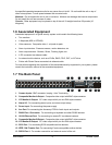
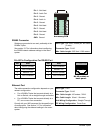
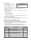
Alarm I/O Port
The back panel of the unit is equipped with an Alarm
Port (DB-25 style connector).
Do not attempt to wire directly to the DB-25
connector on the back panel.
DB-25 Connector on Back Panel
Connect the Alarm PCB (supplied with the unit) to the Alarm Port. Wire all alarm inputs to the Alarm
PCB per the pin out specifications shown below.