


0150-0193G 15 DVMRe Triplex
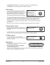
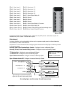
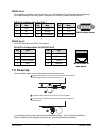
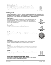
RS232 Port 1
For a Modem connection or remote control of unit. See section 3.17 for information about configuring
the modem settings in the menu system. See section 9 for RS232 Remote Control Protocols.
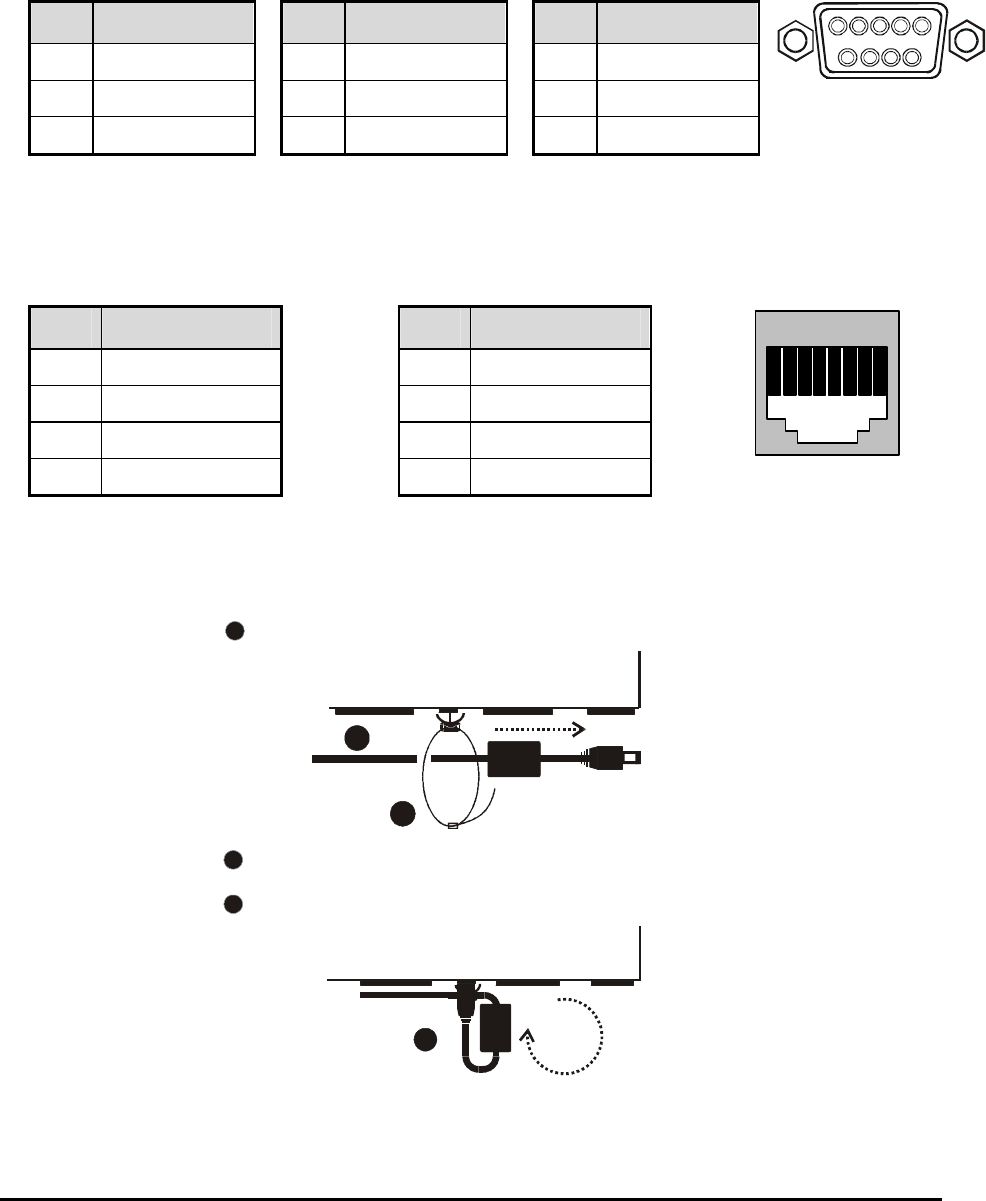
DB-9 Pin Configuration For Port 1
Pin Use
Pin Use
Pin Use
1 DCD 4 DTR 7 RTS
2 RX 5 Ground 8 CTS
3 TX 6 Not Connected 9 Not Connected
1
5
6
9
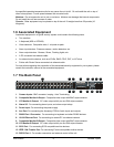
DB-9 on back panel.
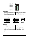
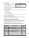
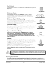
RS232 Port 2
For Event Generation and ASCII Text Insertion.
RJ-45 Pin Configuration For RS232 Port 2
Pin Use
Pin Use
1 Ground 5 TXD
2 Reserved 6 Not Connected
3 Not Connected 7 Ground
4 RXD 8 Reserved
82 3 4 5 6 71
RJ-45 socket on
back panel.
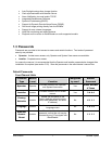
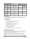
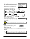
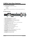
1.8 Power-Up
Use the diagram below to secure the power cord to the back panel.
2
1
3
Slide approximately 6 inches of the power cord through the pre-installed
cable tie (approximately 1 inch after the ferrite core).
Tighten the cable tie until the cord is secure. Do not over tighten.
Loop the power cord end around and insert into the power receptacle on
the back panel.
2
1
3
It is important that the power-up procedures be followed carefully. The unit uses its auto-detect
feature to detect camera signals during power-up, and configure itself automatically.