


0150-0193G 13 DVMRe Triplex
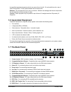
Pin 1: Not Used.
Pin 2: Audio Out.
Pin 3: Ground.
Pin 4: Audio In.
Pin 5: Ground.
Pin 6: Not Used.
Pin 7: Ground.
Pin 8: Not Used.
Pin 9: Ground.
GND: Ground.
1
2
3
4
5
6
7
8
9
GND
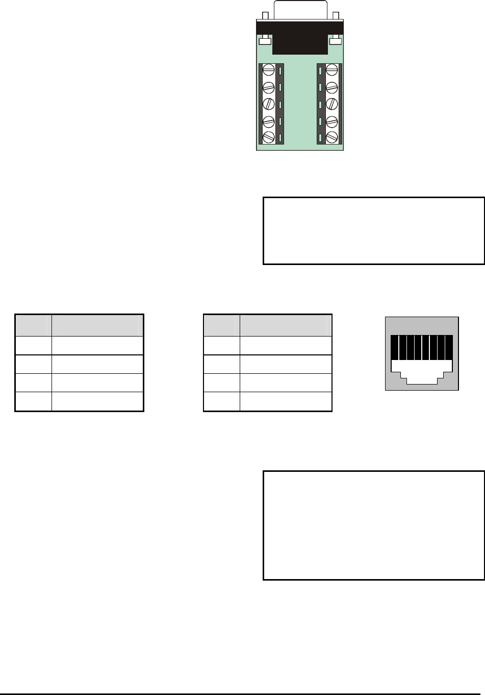
Accessory PCB
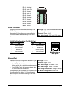
RS485 Connector
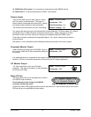
Wire Type:
#24 AWG, twisted pair with shield
(2-wire)
Connector Type: RJ-45
Max. Cable Length: 3200 feet / 1000 meters
Shields are grounded at one end, preferably at the
DVMRe
Triplex.
See section 3.17 for information about configuring
the RS485 network address settings in the menu
system.
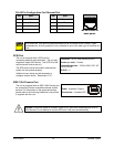
RJ-45 Pin Configuration For RS485 Port
Pin Use
Pin Use
1 Ground (Shield) 5 Not Connected
2 Not Connected 6 Network -VE
3 Network +VE 7 Ground (Shield)
4 Not Connected 8 Not Connected
82 3 4 5 6 71
RJ-45 socket on
back panel.
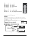
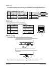
Ethernet Port
Wire Type: Cat 5
Connector Type: RJ-45
Max. Cable Length: 100 meters / 328 ft.
Min. Cable Length: 6 feet / 1.8 meters
Hub Wiring Configuration: Straight Through
PC Wiring Configuration: Cross Over
The cable connection configuration depends on your
network configuration:
• For a DVMRe Triplex that connects directly to a
Hub or Switch, use a straight through connection.
• For a DVMRe Triplex that connects directly to a
PC, use a cross over connection.
Consult with your MIS personnel for the specific type
of configuration. See section 3.17 for information
about configuring the ethernet settings in the menu
system.