


BusSecure User Manual DVR Installation and Wiring
0150-0263A / May 2003 17
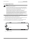
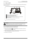
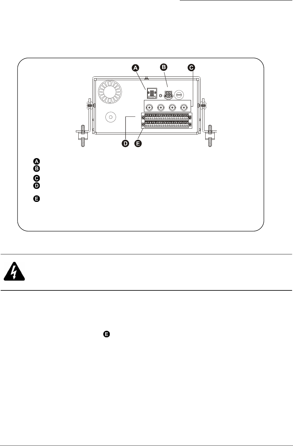
3.2 WIRING THE DVR
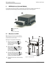
All wire connections between the DVR and auxiliary devices are made through the DVR’s Rear Panel
Assembly (see Figure 22).
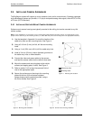
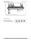
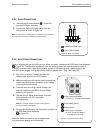
3.2.1.1 P1 TERMINAL BLOCK CONNECTIONS (LOWER CONNECTOR)
The P1 terminal block provides power to the vehicle’s cameras.
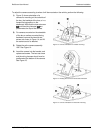
1) Remove the P1 terminal block ( in Figure 22) from the rear panel assembly by loosening its
mounting screws and pulling it out of its socket.
2) Make connections as shown in Figure 23. To make connections, strip each wire 3/8 of an inch,
insert it into the appropriate slot, and tighten the terminal screw.
3) Reinstall the P1 terminal block.
1 2 3 4 5 6 7 8 9 10 11 12 13 14 15 16 17 18 19 20
P2
GND
CAM1
ETHERNET
10/100
POWER
FUSE
CAM2 CAM3 CAM4
P1
Ethernet connector (Use of this connector is optional)
Four-pin Molex (power management board)
BNC connectors (Video inputs Cam 1 – Cam 4)
P2 Terminal Block (Alarm inputs/outputs, status indication, and impact sensor)
(Upper Connector)
P1 Terminal Block (Camera connections) (Lower Connector)
Figure 22. DVR Rear Panel Assembly connections
CAUTION:
Be very careful that you do not confuse the P1 terminal block with the P2 terminal block. The P2
terminal block is positioned above the P1 terminal block. The P1 terminal block is used strictly for
camera connections; the P2 terminal block is used strictly for input/output wiring.