


DVR Installation and Wiring BusSecure User Manual
20 0150-0263A / May 2003
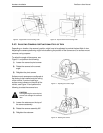
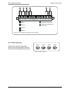
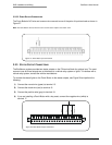
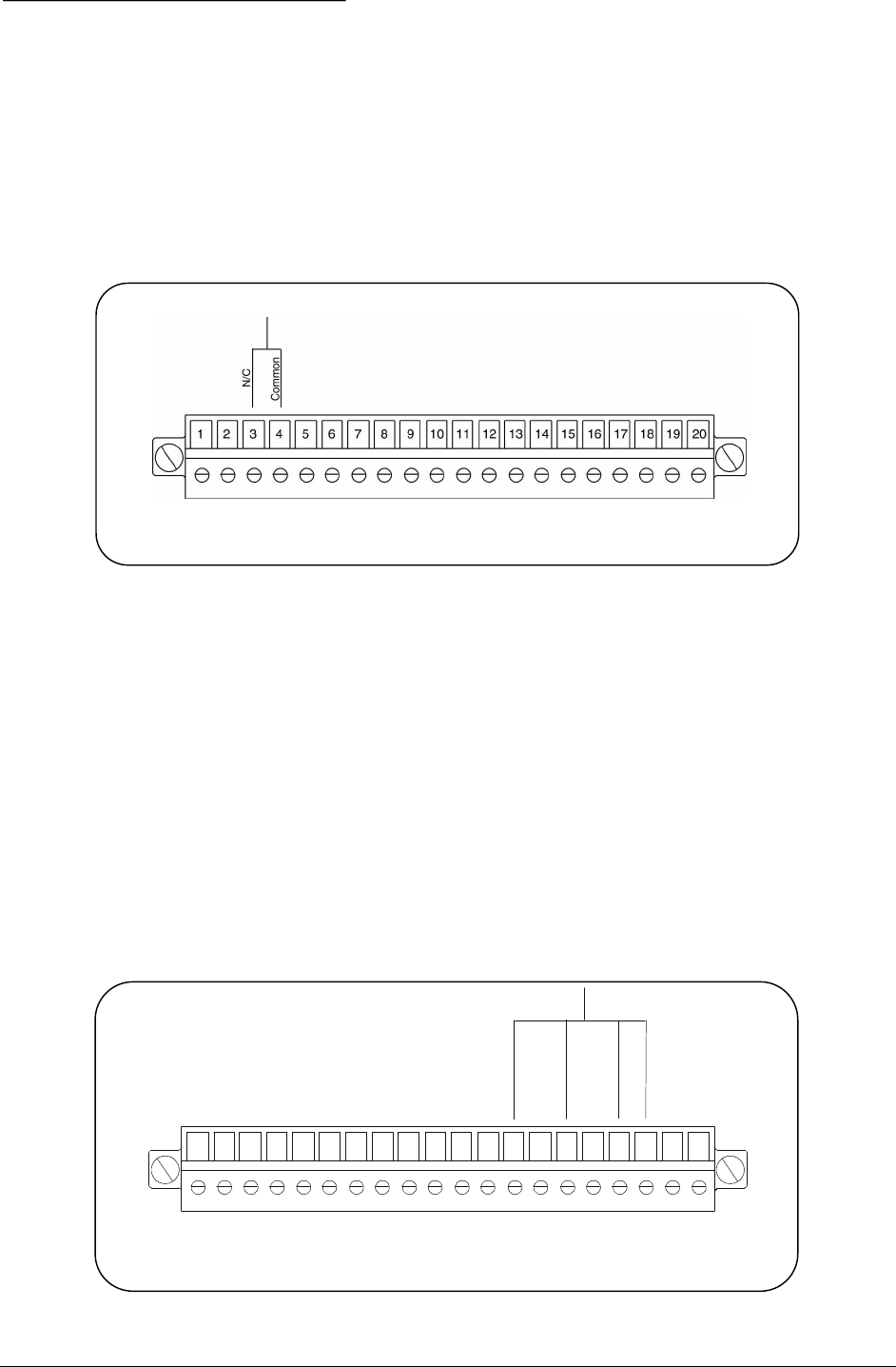
3.2.2.2 PANIC BUTTON CONNECTIONS
The Panic Button’s N/C wire and common wire connect to one of the pairs of input terminals as shown in
Figure 27.
Note: The Panic Button also has wires that are used for status outputs. See section 3.2.4.
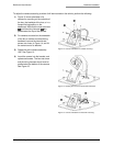
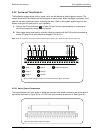
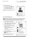
3.2.3 STATUS OUTPUT CONNECTIONS
The BusSecure system provides two status outputs on the P2 terminal block for optional use. The most
common uses for these outputs are as interfaces to a vehicle relay system or lights. To interface with a
vehicle relay system, contact the vehicle manufacturer.
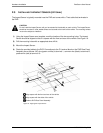
To connect the status lights on the Panic Button to the status outputs, see Figure 28 and perform the
following:
1) Connect the normal wire (green) to terminal 13.
2) Connect the check wire (red) to terminal 15.
3) Connect the positive wire (gray) to terminal 18.
4) If you are installing a Panic Button with a key reset, connect the negative wire (white) to
terminal 17.
1
2
3
4
5
6
7
8
9
10 11 12 13 14 15
16
17
18
19
20
N
o
r
m
a
l
C
h
e
c
k
G
N
D
P
o
s
i
t
i
v
e
Figure 27. Panic Button input connections
Figure 28. Panic Button output connections