


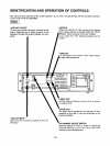

IDENTIFICATION AND OPERATION OF CONTROLS
Now that you have experienced the simple operation of your VCR, let's get familiar with the complete operation
of your VCR and all its capabilities.
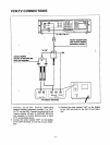
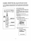
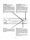
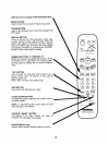
[ REAR [
"VHF/UHF OUTPUT"
75-ohm round Cable Connector connects to this
output. Opposite end of cable connects to the
television through the Antenna Splitter (not sup-
plied).
AUDIO IN
When this "AUDIO IN" jack, receive audio signals
from a Video Camera or another VCR, the "INPUT
VSELECT" button must be in the "AN" position.
If you select AN, "AV" indicator appears on the
screen.
"VIDEO IN"
connection from another VCR, video camera
other video equipment.
OUT TO TV
IN FROM ANT
IIIIII F
I J
"VHF/UHF INPUT"
Lead wire from antenna connects to this 75-
ohm input
@
Permits video connection of your unit to a monitor
or another VCR.
"AUDIO OUT"
The audio that is supplied to the television is also
available at this jack. It can be connected to an
external amplifier.
CHANNEL SELECT SWITCH
Slide the switch to "CH3" or "CH4" to match the
channel selector on your TV. This is the VCR
channel on your television set.
-15-