7
OVERVIEW
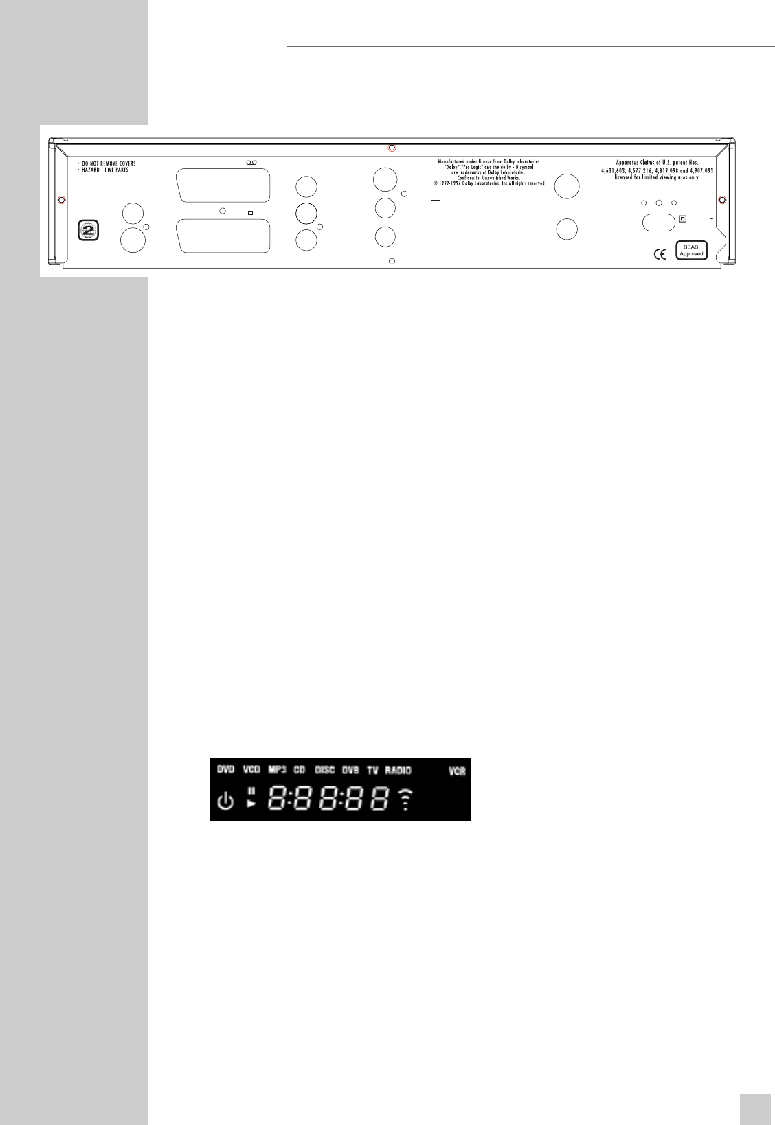
The back of the Receiver/Player
RF IN Connector for TV aerial.
RF OUT 1 & 2 Connector for VCR and second TV RF outputs.
AUDIO OUT L R Audio output jacks (left/right channel) for connection
to a HiFi system.
TV SCART Video/audio output jack for connecting a television
VCR SCART set and a VCR.
DIGITAL AUDIO OUT Audio output jack (coaxial) for
PCM/MPEG2/AC3/DTS signals, for connecting a
digital multichannel audio/video amplifier.
VIDEO OUT Composite video output jack.
S-VIDEO OUT Super VHS output jack.
220-240V ~ 50/60 Hz 20W Socket for power cord.
Caution:
Do not connect any devices while the Receiver/Player is switched on.
Never touch the inside of the sockets and plugs of the connecting cables.
An electrostatic discharge can damage the Receiver/Player.
The display elements of the Receiver/Player
»
!
« Playback.
»
❙❙
« Pause/Freeze-Frame.
»DVD« DVD inserted.
»CD« CD inserted.
»VCD« VCD inserted.
»MP3« MP3 inserted.
»0:00:00« Total or elapsed playing time in hours, minutes and seconds.
»DVB« Receiving a Digital service.
»TV« Outputting TV signal.
»RADIO« Outputting RADIO signal
»VCR« Outputting VCR recording.
VIDEO OUT
S-VIDEO
VCR
TV
RF IN
RF OUT - 1
RF OUT - 2
9V DC
50mA max
AERIAL IN
LOOP
THROUGH
MADE IN U.K.
220-240 V
50/60 Hz 25 W
AUDIO OUT
DIGITAL
L
R


