3654 Portable H2/N2 Analyzer - Maintenance and Troubleshooting 47 of 66
Operator Manual
ORBISPHERE
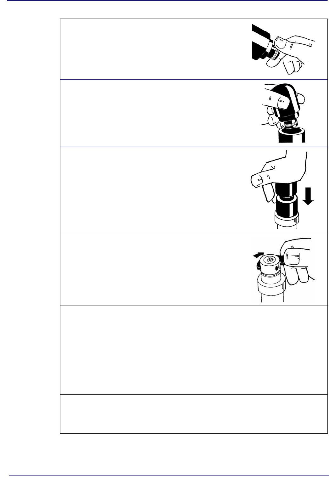
Place the membrane holding ring on the installation tool
tip.
CAUTION:
To avoid damaging the membrane, make sure that the
tool tip is totally clean and its surface is even.
Insert the installation tool inside the guiding sleeve.
Push the installation tool firmly downwards. This clasps
the mounting ring onto the sensor head, folding the
membrane over the sensor tip.
Remove the installation tool and guiding sleeve.
Visually check for correct ring placement, try to push it
down with your fingers.
Check that the membrane is tight, with no wrinkles.
Clean and dry the protection cap ready for installation.
Replace the O-ring inside the protection cap with a new
one. Tighten the protection cap finger tight.
Then, complete the process using the tool provided in the
maintenance kit. Insert into each of the four holes in turn,
and tighten as far as possible. Tighten each hole only
once.
Finally replace the flow chamber.
Gently lower the flow chamber onto the sensor, guiding
the thermistor on the sensor into the hole in the flow
chamber base.
Turn the flow chamber locking pin (see Fig 1-1 on page 9)
clockwise to secure it in place.
CAUTION:
The thermistor is used to measure the sample
temperature. Do not bend or damage this component.
Check that the membrane has not been damaged. The
alarm message “ERR” will be displayed on your analyzer
if the membrane leaks in any way.


