14 Setup
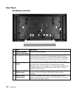
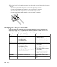
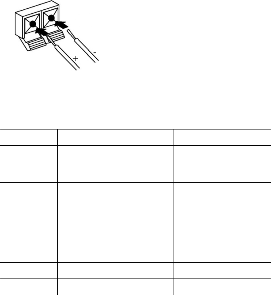
4 Press down the tab for the speaker connector, insert the speaker wire and release the tab to secure
the wire:
• Connect the right speaker red (positive +) wire to the right red (+) connector.
• Connect the right speaker black (negative –) wire to right black (–) connector.
• Connect the left speaker red (positive +) wire to the left red (+) connector.
• Connect the left speaker black (negative –) wire to left black (–) connector.
Identifying Your Component’s Cables
Where you connect your component into the connectors depends on the type of component and
cables you are using. Your TV is compatible with composite, component, S-video, DVI-D, or VGA
cables. Use the following chart to determine your component type:
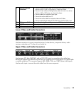
Type of
Component
Description of Cable(s) Where to Connect
Composite One three headed cable:
• One yellow for video
• One red for audio
• One white for audio
• Insert the yellow cable into the
yellow AV video in.
• Insert the red and white cables into
the red and white audio inputs.
S-video One cable with 4 pins. Insert the cable into the S-video in.
Component Three or five headed cable:
• One red for Pr signal
• One green for Y signal
• One blue for Pb signal
Some component cables come with red and
white audio cables attached.
• Insert the red cable into the red
YPbPr video in.
• Insert the green cable into the
green YPbPr video in.
• Insert the blue cable into the blue
YPbPr video in.
• Insert the red and white audio
cables into the red and white
YPbPr audio inputs.
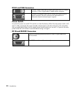
DVI-HDCP One cable with 3 rows of 8 pins. Insert the cable into the DVI video
input.
VGA One cable with 3 rows of 5 pins. Insert the cable into the VGA video
input.


