16
Accessory Audio/Video
Connections
Notes:
• Pictures containing copy protection signals that
prohibit any copying cannot be recorded.
• If you pass the recorder signals via the VCR, you
may not receive a clear image on your TV screen.
Be sure to connect your VCR to the recorder and
your TV in the order shown below. To watch video
tapes, watch the tapes through a second line input on
your TV.
• If you disconnect the recorder’s mains lead, you will
not be able to view the signals from the connected
VCR or tuner.
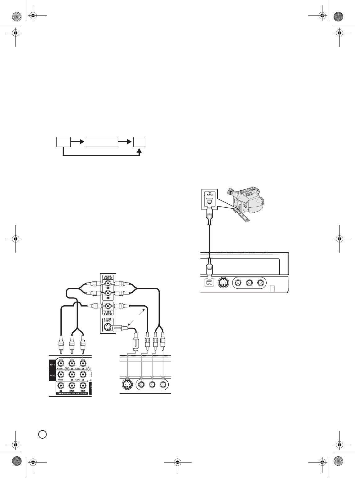
Connecting to the INPUT 1 or INPUT 2
Jacks
Connect the input jacks (AV1 IN, AV2 IN) on the
recorder to the audio/video out jacks on your accessory
component, using audio/video cables.
Note:
If you use the S-VIDEO IN jack on the front panel, the
VIDEO IN jack on the front panel is not available.
Connecting a Digital Camcorder
Using the front panel DV IN jack, it is possible to
connect a DV digital camcorder and digitally transfer
DV tapes to DVD.
Use a DV cable (not supplied) to connect the DV in/out
jack of your DV camcorder to the front panel DV IN jack
of this recorder.
(See page 43 for operating input switch.)
Notes:
• This jack is for connection to DV digital camcorder
only. It is not compatible with digital satellite tuners or
D-VHS video decks.
• The DV IN jack cannot be used to connect some
devices.
• No copy-guarded signal can be recorded.
• When you turn the recorder on after connecting the
DV cable, the recorder may not recognize the DV
digital camcorder.
VCR RECORDER
Line input 1
Line input 2
TV
Jack panel of Accessory Component
(VCR, Camcorder, etc.)
OR
Rear of
the recorder
Front of
the recorder
DV Digital Camcorder
Front of the recorder
01EN01DVDS253A(AU).book Page 16 Wednesday, June 7, 2006 3:39 PM


