


SPYDER® BACNET® PROGRAMMABLE CONTROLLERS
11 63-2689—05
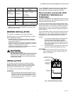
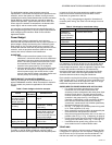
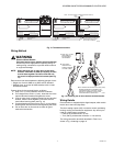
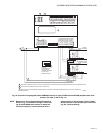
Fig. 13. Termination modules.
Wiring Method
WARNING
Electrical Shock Hazard.
Can cause severe injury, death or property damage.
Disconnect power supply before beginning wiring, or
making wiring connections, to prevent electrical shock
or equipment damage.
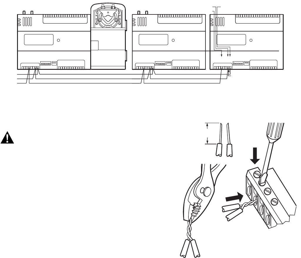
NOTE: When attaching two or more wires to the same
terminal, other than 14 AWG (2.0 sq mm), be sure
to twist them together. Deviation from this rule
can result in improper electrical contact (see Fig.
14).
Each terminal can accommodate the following gauges of wire:
— Single wire: from 22 AWG to 14 AWG solid or stranded
— Multiple wires: up to two 18 AWG stranded, with 1/4 watt
wire-wound resistor
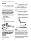
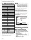
Prepare wiring for the terminal blocks, as follows:
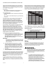
1. Strip 1/2 in. (13 mm) insulation from the conductor.
2. Cut a single wire to 3/16 in. (5 mm). Insert the wire in the
required terminal location and tighten the screw.
3. If two or more wires are being inserted into one terminal
location, twist the wires together a minimum of three
turns before inserting them (see Fig. 14).
4. Cut the twisted end of the wires to 3/16 in. (5 mm) before
inserting them into the terminal and tightening the screw.
5. Pull on each wire in all terminals to check for good
mechanical connection.
Fig. 14. Attaching two or more wires at terminal blocks.
Wiring Details
Each controller is shipped with the digital outputs, which switch
the 24 Vac to the load (High Side).
The three analog outputs (AO) are used to control modulating
heating, cooling and economizer equipment. Any AO may be
used as a digital output, as follows:
— False (0%) produces 0 Vdc, (0 mA)
— True (100%) produces the maximum 11 Vdc (22 mA)
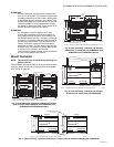
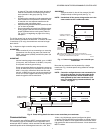
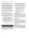
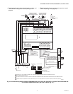
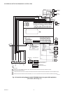
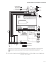
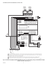
The wiring connection terminals described in Table 7 are
shown in Fig. 15 starting on page 12.
AO-1
COM
AO-2
AO-3
COM
UI-1
COM
UI-2
UI-3
COM
UI-4
UI-5
COM
UI-6
DI-1
DI-2
COM
DI-3
20V DC
DI-4
BAC –
BAC +
SHLD
EGND
24 VAC
24VAC COM
DO-1
COM
DO-2
DO-3
DO-4
DO-5
COM
DO-6
COM
M29331
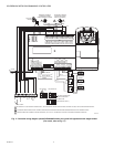
ADD APPROPRIATE TERMINATION
RESISTOR BETWEEN THE BAC+
AND THE BAC– TERMINALS.
BACnet MS/TP–
BAC+
SHLD
BAC–
NOTE: ALL BACnet MS/TP CONNECTIONS ARE MADE TO:
1
2
3 4 5 6
7 8
1 0 9 2 3 4 5 6 7 8 0 9
1 1 1 1 1 1 1 1 1 2 1
1
2
3 4
5
6
7 8
0
9
2
2 2
2 2
2
2
2 2
3
3
1
2
3 4
5
6
7 8
0
9
3
3
3
3 3
3 3
3 4
AO-1
COM
AO-2
AO-3
COM
UI-1
COM
UI-2
UI-3
COM
UI-4
UI-5
COM
UI-6
DI-1
DI-2
COM
DI-3
20V DC
DI-4
BAC –
BAC +
SHLD
EGND
24 VAC
24VAC COM
DO-1
COM
DO-2
DO-3
DO-4
DO-5
COM
DO-6
COM
1
2
3 4 5 6
7 8
1 0 9 2 3 4 5 6 7 8 0 9
1 1 1 1 1 1 1 1 1 2 1
1
2
3 4
5
6
7 8
0
9
2
2 2
2 2
2
2
2 2
3
3
1
2
3 4
5
6
7 8
0
9
3
3
3
3 3
3 3
3 4
DO-7
DO-8
COM
DO-7
DO-8
COM
SBUS1
SBUS2
SBUS1
SBUS2
SBUS1
SBUS2
BACnet MS/TP+
SHIELD
BACnet MS/TP–
BACnet MS/TP+
SHIELD
1/2
(13)
STRIP 1/2 IN. (13 MM)
FROM WIRES TO
BE ATTACHED AT
ONE TERMINAL.
1.
2.
TWIST WIRES
TOGETHER WITH
PLIERS (A MINIMUM
OF THREE TURNS).
3.
CUT TWISTED END OF WIRES TO 3/16 IN. (5 MM)
BEFORE INSERTING INTO TERMINAL AND
TIGHTENING SCREW. THEN PULL ON EACH
WIRE IN ALL TERMINALS TO CHECK FOR
GOOD MECHANICAL CONNECTION.
M17207