


SPYDER® BACNET® PROGRAMMABLE CONTROLLERS
63-2689—05 8
required and thereby affect transformer sizing. The following
example is an I x R line-loss calculation for a 200 ft. (61m) run
from the transformer to a controller drawing 37 VA and using
two 18 AWG (1.0 sq mm) wires.
The formula is:
Loss = [length of round-trip wire run (ft.)] x [resistance in
wire (ohms per ft.)] x [current in wire (amperes)]
From specification data:
18 AWG twisted pair wire has a resistance of 6.52 ohms per
1000 feet.
Loss = [(400 ft.) x (6.52/1000 ohms per ft.)] x [(37 VA)/(24V)]
= 4.02 volts
This means that four volts are going to be lost between the
transformer and the controller. To assure the controller
receives at least 20 volts, the transformer must output more
than 24 volts. Because all transformer output voltage levels
depend on the size of the connected load, a larger transformer
outputs a higher voltage than a smaller one for a given load.
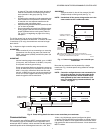
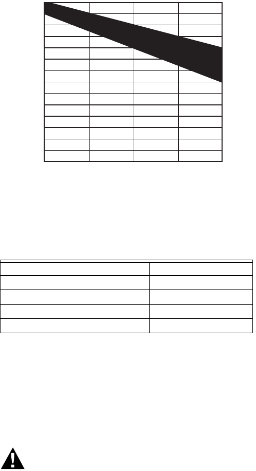
Fig. 10 shows this voltage load dependence.
In the preceding I x R loss example, even though the controller
load is only 37 VA, a standard 40 VA transformer is not
sufficient due to the line-loss. Looking at Fig. 10, a 40 VA
transformer is just under 100 percent loaded (for the 37 VA
controller) and has a secondary voltage of 22.9 volts. (Use the
lower edge of the shaded zone in Fig. 10 that represents the
worst case conditions.) When the I x R loss of four volts is
subtracted, only 18.9 volts reaches the controller. This is not
enough voltage for proper operation.
In this situation, the engineer has three alternatives:
1. Use a larger transformer. For example, if an 80 VA model
is used, an output of 24.4 volts, minus the four volt line-
loss, supplies 20.4V to the controller (see Fig. 10).
Although acceptable, the four-volt line-loss in this exam-
ple is higher than recommended.
IMPORTANT
No installation should be designed where the line-loss
is greater than two volts. This allows for nominal oper-
ation if the primary voltage drops to 102 Vac (120 Vac
minus 15 percent).
2. Use heavier gauge wire for the power run. 14 AWG
(2.0 sq mm) wire has a resistance of 2.57 ohms per
1,000 ft. Using the preceding formula results in a line-
loss of only 1.58 volts (compared with 4.02 volts). This
would allow a 40 VA transformer to be used. 14 AWG
(2.0 sq mm) wire is the recommended wire size for 24
Vac wiring.
3. Locate the transformer closer to the controller. This
reduces the length of the wire run, and the line-loss.
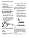
The issue of line-loss is also important in the case of the output
wiring connected to the Triac digital outputs. The same formula
and method are used. Keep all power and output wire runs as
short as practical. When necessary, use heavier gauge wire, a
bigger transformer, or install the transformer closer to the
controller.
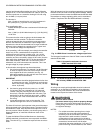
To meet the National Electrical Manufacturers Association
(NEMA) standards, a transformer must stay within the NEMA
limits. The chart in Fig. 10 shows the required limits at various
loads.
With 100 percent load, the transformer secondary must supply
between 23 and 25 volts to meet the NEMA standard. When a
purchased transformer meets the NEMA standard DC20-1986,
the transformer voltage regulating ability can be considered
reliable. Compliance with the NEMA standard is voluntary.
Fig. 10. NEMA Class 2 transformer voltage output limits.
The Honeywell transformers listed in Table 5 meet the NEMA
standard DC20-1986.
Table 5. Honeywell transformers that meet
NEMA standard DC20-1986.
NOTE: The AT88A and AT92A transformers do not meet
the voluntary NEMA standard DC20-1986.
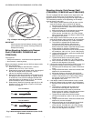
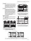
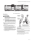
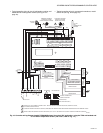
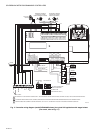
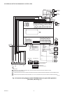
Wiring
All wiring must comply with applicable electrical codes and
ordinances, or as specified on installation wiring diagrams.
Controller wiring is terminated to the screw terminal blocks
located on the top and the bottom of the device.
WARNING
Electrical Shock Hazard.
Can cause severe injury, death or property damage.
Disconnect power supply before beginning wiring or
making wiring connections, to prevent electrical shock
or equipment damage.
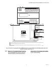
NOTES:
— For multiple controllers operating from a single
transformer, the same side of the transformer
secondary must be connected to the same power
input terminal in each controller. Controller
configurations will not necessarily be limited to
three devices, but the total power draw, including
accessories, cannot exceed 100 VA when
powered by the same transformer (U.S. only). For
power and wiring recommendations, See “Power”
Transformer Type VA Rating
AT40A 40
AT72D 40
AT87A 50
AK3310 Assembly 100
27
26
25
24
23
22
21
20
19
18
17
16
15
14
0 50 100 150
% OF LOAD
SECONDARY VOLTAGE
200
M993