


SPYDER® BACNET® PROGRAMMABLE CONTROLLERS
3 63-2689—05
BEFORE INSTALLATION
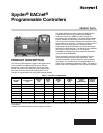
The controller is available in three models (see Table 1).
Review the power, input, and output specifications on page 2
before installing the controller.
— Hardware driven by Triac outputs must have a minimum
current draw, when energized, of 25 mA and a maximum
current draw of 500 mA.
— Hardware driven by the analog current outputs must have a
maximum resistance of 550 Ohms, resulting in a maximum
voltage of 11 volts when driven at 20 mA.
If resistance exceeds 550 Ohms, voltages up to 18 Vdc are
possible at the analog output terminal.
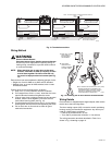
WARNING
Electrical Shock Hazard.
Can cause severe injury, death or property damage.
Disconnect power supply before beginning wiring or
making wiring connections to prevent electrical shock
or equipment damage.
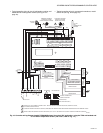
INSTALLATION
The controller must be mounted in a position that allows
clearance for wiring, servicing, removal, connection of the
BACnet MS/TP Molex connector and access to the MS/TP
MAC address DIP switches (see Fig. 15 on page 12).
The controller may be mounted in any orientation.
IMPORTANT
Avoid mounting in areas where acid fumes or other
deteriorating vapors can attack the metal parts of the
controller, or in areas where escaping gas or other
explosive vapors are present. Fig. 6–Fig. 7 on page 5
for mounting dimensions.
For the PVB6436AS model, the actuator is mounted first and
then the controller is mounted. For the other models, go to
“Mount Controller” on page 5 to begin the installation.
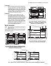
Mount Actuator onto Damper Shaft
(PVB0000AS, PVB4022AS and
PVB6436AS)
PVB0000AS, PVB4022AS and PVB6436AS controllers include
the direct-coupled actuator with Declutch mechanism, which is
shipped hard-wired to the controller.
The actuator mounts directly onto the VAV box damper shaft
and has up to 44 lb-in. (5 Nm) torque, 90-degree stroke, and 90
second timing at 60 Hz. The actuator is suitable for mounting
onto a 3/8 to 1/2 in. (10 to 13 mm) square or round VAV box
damper shaft. The minimum VAV box damper shaft length is 1-
9/16 in. (40 mm).
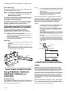
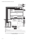
The two mechanical end-limit set screws control the amount of
rotation from 12° to 95°. These set screws must be securely
fastened in place. To ensure tight closing of the damper, the
shaft adapter has a total rotation stroke of 95° (see Fig. 1).
NOTES:
1. The actuator is shipped with the mechanical end-
limit set screws set to 95 degrees of rotation.
Adjust the two set screws closer together to
reduce the rotation travel. Each “hash mark” indi-
cator on the bracket represents approximately 6.5°
of rotation per side.
2. The Declutch button, when pressed, allows you to
rotate the universal shaft adapter (see Fig. 1).
IMPORTANT
Determine the damper rotation and opening angle
prior to installation. See Fig. 2 below and Fig. 3 on
page 4 for examples.
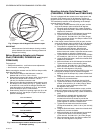
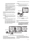
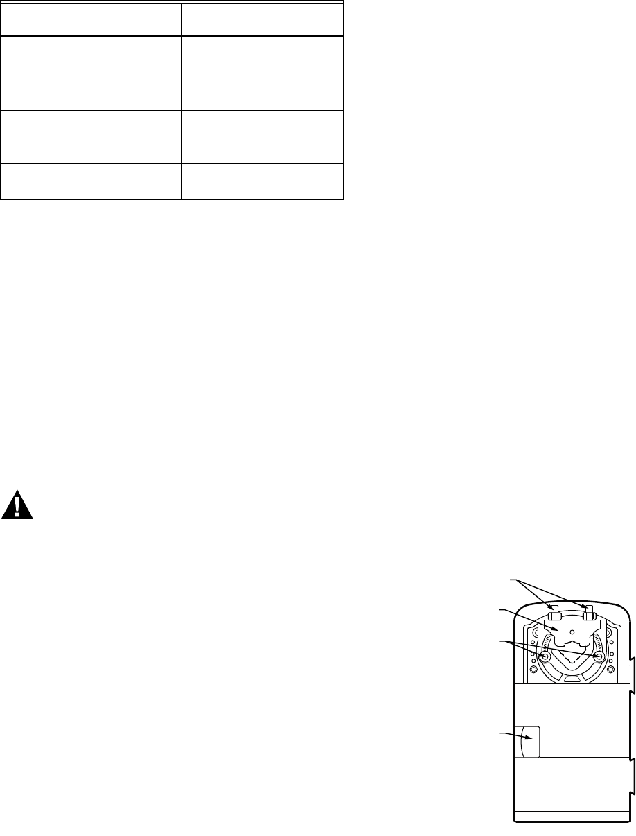
Fig. 1. Series 60 Floating Actuator.
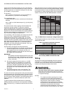
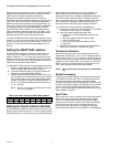
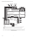
TR23
Setpoint
Potentiometer
500 Ohm
to
10,500 Ohm
-4° DDC to +4° DDC
(-8° DDF to +7° DDF)
or
50 F to 90 F
(10 C to 32 C)
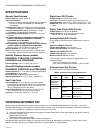
Resistive Input Generic 100 Ohms to 100K Ohms
Voltage
Input
Transducer,
Controller
0–10 Vdc
Discrete Input Dry Contact
closure
Open Circuit > 3000 Ohms
Closed Circuit < 3000 Ohms
a
C7031G and C7041F are recommended for use with these
controllers, due to improved resolution and accuracy when
compared to the PT1000.
Input
Type
Sensor
Type
Operating
Range
UNIVERSAL SHAFT
CLAMPING BOLTS (2)
M23568
UNIVERSAL
SHAFT ADAPTER
MECHANICAL
END LIMIT SET
SCREWS (2)
DECLUTCH
BUTTON