


SPYDER® BACNET® PROGRAMMABLE CONTROLLERS
9 63-2689—05
on page 6. The earth ground terminal (terminal 3)
must be connected to a verified earth ground for
each controller in the group (see Fig. 12 on
page 9).
— All loads on the controller must be powered by the
same transformer that powers the controller itself.
A controller can use separate transformers for
controller power and output power.
— Keep the earth ground connection (terminal 3) wire
run as short as possible.
— Do not connect the universal input COM terminals,
analog output COM terminals or the digital input/
output COM terminals to earth ground. Refer to
Fig. 16–Fig. 21 beginning on page 13 for wiring
examples.
The 24 Vac power from an energy limited Class II power
source must be provided to the controller. To conform to Class
II restrictions (U.S. only), the transformer must not be larger
than 100 VA.
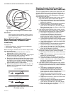
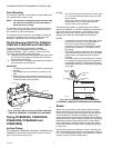
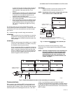
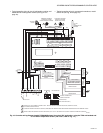
Fig. 11 depicts a single controller using one transformer.
IMPORTANT
Power must be off prior to connecting to or removing
connections from the 24 Vac power (24 Vac/24 Vac
COM), earth ground (EGND), and 20 Vdc power (20
Vdc) terminals.
IMPORTANT
Use the heaviest gauge wire available, up to 14 AWG
(2.0 sq mm), with a minimum of 18 AWG (1.0 sq mm),
for all power and earth ground wiring.
Screw-type terminal blocks are designed to accept up
to one 14 AWG (2.0 sq mm) conductor or up to two 18
AWG (1.0 sq mm) conductors. More than two wires
that are 18 AWG (2.0 sq mm) can be connected with
a wire nut. Include a pigtail with this wire group and
attach the pigtail to the terminal block.
IMPORTANT
Connect terminal 2, (the 24 Vac common [24 VAC
COM] terminal) to earth ground (see Fig. 11).
NOTE: Unswitched 24 Vac power wiring can be run in the
same conduit as the L
ONWORKS® cable.
Fig. 11. Power wiring details for one controller per
transformer.
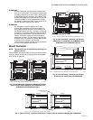
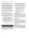
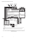
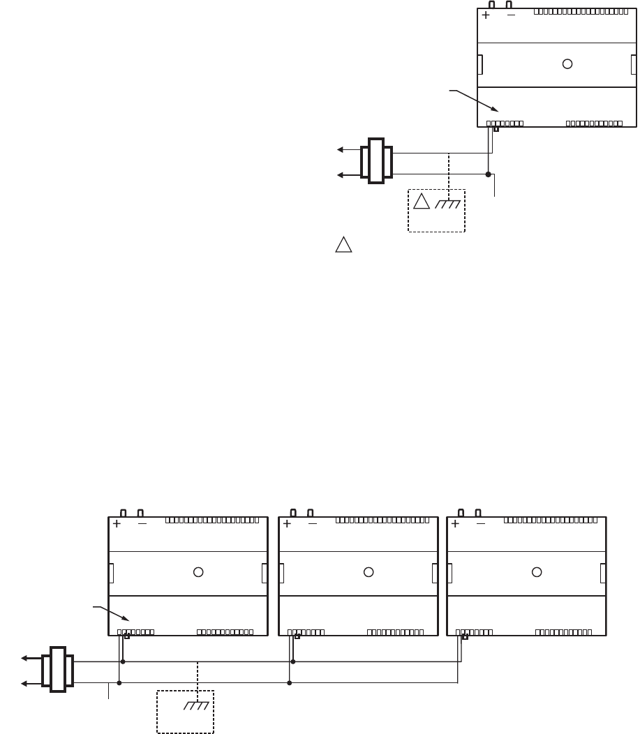
More than one controller can be powered by a single
transformer. Fig. 12 shows power wiring details for multiple
controllers.
NOTE: Controller configurations are not necessarily lim-
ited to three devices, but the total power draw,
including accessories, cannot exceed 100 VA
when powered by the same transformer (U.S.
only). For power wiring recommendations, see
“Power” on page 6.
Fig. 12. Power wiring details for two or more controllers per transformer.
Communications
Each controller uses a BACnet MS/TP communications port.
The controller’s data is presented to other controllers over a
twisted-pair MS/TP network, which uses the EIA-485 signaling
standard capable of the following baud rates: 9.6, 19.2, 38.4,
76.8 or 115.2 kilobits per second (configured at global
controller). The Spyder BACnet controllers are master devices
on the MS/TP network. Each Spyder BACnet controller uses a
high-quality EIA-485 transceiver and exerts 1/4 unit load on the
MS/TP network.
M29684A
TRANSFORMER
OUTPUT
DEVICE
POWER
ΔP
1
2
3456
78
109 2345678 09
11 1111111 21
1
2
34
5
6
78
0
9
2
22
22
2
2
22
3
3
1
2
34
5
6
78
0
9
3
3
3
33
33
34
EARTH
GROUND
1
LINE VOLTAGE
GREATER
THAN 150 VAC
WHEN CONNECTIONG POWER TO THE SPYDER BACnet
CONTROLLER, CONNECT THE COM LEG OF THE VAC SECONDARY
CIRCUIT TO A KNOWN EARTH GROUND.
1
COM
24 VAC
CONNECT POWER TO
TERMINALS 1 AND 2
M29685A
120/240
VAC
TRANSFORMER
OUTPUT
DEVICE
POWER
ΔP
1
2
3456
78
109 2345678 09
11 1111111 21
1
2
34
5
6
78
0
9
2
22
22
2
2
22
3
3
1
2
34
5
6
78
0
9
3
3
3
33
33
34
COM
24 VAC
ΔP
1
2
3456
78
109 2345678 09
11 1111111 21
1
2
34
5
6
78
0
9
2
22
22
2
2
22
3
3
1
2
34
5
6
78
0
9
3
3
3
33
33
34
ΔP
1
2
3456
78
109 2345678 09
11 1111111 21
1
2
34
5
6
78
0
9
2
22
22
2
2
22
3
3
1
2
34
5
6
78
0
9
3
3
3
33
33
34
CONNECT POWER TO
TERMINALS 1 AND 2
EARTH
GROUND