


SPYDER® BACNET® PROGRAMMABLE CONTROLLERS
19 63-2689—05
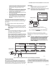
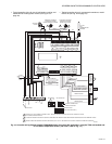
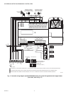
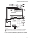
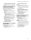
Fig. 22. Controller wiring diagram (model PUB6438S
shown) for RP7517B pneumatic transducer.
CHECKOUT
Step 1. Check Installation and Wiring
Inspect all wiring connections at the controller terminals, and
verify compliance with installation wiring diagrams. If any wiring
changes are required, first be sure to remove power from the
controller before starting work. Pay particular attention to:
— 24 Vac power connections. Verify that multiple controllers
being powered by the same transformer are wired with the
transformer secondary connected to the same input
terminal numbers on each controller. Use a meter to
measure 24 Vac at the appropriate terminals (see Fig. 12
on page 9). Controller configurations are not necessarily
limited to three devices, but the total power draw, including
accessories, cannot exceed 100 VA when powered by the
same transformer (U.S. only).
— Be sure that each controller has terminal 3 wired to a
verified earth ground, using a wire run as short as possible
with the heaviest gauge wire available, up to 14 AWG (2.0
sq mm) with a minimum of 18 AWG (1.0 sq mm) for each
controller in the group (see Fig. 12 on page 9).
— Check that the MS/TP network polarity has been connected
properly on each controller. BACnet MS/TP is polarity
sensitive; communication will be lost for the entire segment
if one controller is connected improperly (see Fig. 13 on
page 11).
— Verify that Triac wiring of the digital outputs to external
devices uses the proper load power and 24 Vac common
terminal (digital output common terminals) for High-Side
switching.
NOTE: All wiring must comply with applicable electrical
codes and ordinances or as specified on installa-
tion wiring diagrams.
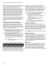
For guidelines for wiring run lengths and power budget, see
“Power” on page 6.
VERIFY END-OF-LINE TERMINATION RESISTOR
PLACEMENT
The installation wiring diagrams should indicate the locations
for placement of the end of line termination resistors. See
Fig. 13 on page 11.
Correct placement of the end-of-line termination resistors is
required for proper L
ONWORKS® Bus communications.
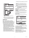
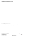
Step 2. Startup
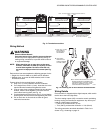
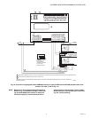
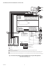
Refer to Fig. 23 and the following text for startup information.
Fig. 23. LED, service, and network connection locations.
SET THE MS/TP MAC ADDRESS
The MS/TP MAC address DIP switches are used to set the
unit's MAC address. Each Spyder BACnet on an MS/TP
network must have a unique MAC address in the range of 0-
127 (address 0 should be avoided as it is the Honeywell factory
default MAC address for all MS/TP devices).
CONTROLLER STATUS LED:
The LED on the front of the controller provides a visual
indication of the status of the device. When the controller
receives power, the LED appears in one of the following
allowable states, as described in Table 8.
AO-1
COM
AO-2
AO-3
COM
UI-1
COM
UI-2
UI-3
COM
UI-4
UI-5
COM
UI-6
DI-1
DI-2
COM
DI-3
20V DC
DI-4
NET-2
NET-1
SHLD
EGND
24 VAC
24VAC COM
DO-1
COM
DO-2
DO-3
DO-4
DO-5
COM
DO-6
COM
1
2
3456
78
109 2345678 09
11 1111111 21
1
2
34
5
6
78
0
9
22 2222222 33
1
2
34
5
6
78
0
9
333333334
M29339B
24 VAC
AO1
24 VAC
COM
1
2
USE 1/4 IN (6 MM) PNEUMATIC TUBING. MINIMUM BRANCH LINE
MUST BE 6 FT. (1.8M) OR LONGER.
TERMINALS 21, 23, AND 24 ARE ANALOG OUTPUTS.
+
-
BLUE
BLACK
BROWN
PNEUMATIC
VALVE
ACTUATOR
RP7517B
1M
2B
M
2
1
DO-7
DO-8
COM
SBUS1
SBUS2
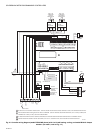
BACnet MS/TP MAC
ADDRESS DIP SWITCHES
TERMINALS 1-8
TERMINALS 9-20
TERMINALS 21-40
AO-1
COM
AO-2
AO-3
COM
UI-1
COM
UI-2
UI-3
COM
UI-4
UI-5
COM
UI-6
DI-1
DI-2
COM
DI-3
20V DC
DI-4
NET-2
NET-1
SHLD
EGND
24 VAC
24VAC COM
DO-1
COM
DO-2
DO-3
DO-4
DO-5
COM
DO-6
COM
1
2
3 4 5 6
7 8
1 0 9 2 3 4 5 6 7 8 0 9
1 1 1 1 1 1 1 1 1 2 1
1
2
3 4
5
6
7 8
0
9
2
2 2
2 2
2
2
2 2
3
3
1
2
3 4
5
6
7 8
0
9
3
3
3
3 3
3 3
3 4
M29340A
HOST
STATUS LED
DO-7
DO-8
COM
SBUS1
SBUS2
BACnet
STATUS LED
LOCAL BACnet MS/TP
MOLEX CONNECTOR PINS